Showing posts with label Fire Alarm Relays. Show all posts

Tuesday, November 3, 2026

NFPA 72 Fire Alarm Relay Location: 3-Foot vs. 20-Foot Rule

NFPA 72 (2025) Fire Alarm Relay Location: When Does the 3-Foot Rule Become 20 Feet?

Updated November 2026. The 2025 edition of NFPA 72 changes a practical detail that can affect fire alarm submittals, rough-in, coordination, and final inspection: the permitted separation between certain emergency control function interfaces and the equipment they control.

In earlier editions, designers commonly worked around a 3-foot proximity rule for emergency control function interfaces when the control circuit was not Class D. In the 2025 edition, Section 21.2.4.1 introduces a conditional allowance of up to 20 feet when the intervening conductors are installed in metal raceway or metal-armored cable. The Class D exception must also be evaluated separately. This is not permission to place every relay anywhere within 20 feet.

Edition warning: NFPA lists 2025 as its current edition, but a published edition does not automatically govern a project. Confirm the legally adopted edition, local amendments, approved design, equipment listings, and AHJ interpretation before applying this change.

Illustration of a fire alarm emergency control relay enclosure next to an HVAC control cabinet connected by metal conduit.
Conceptual fire alarm relay and HVAC interface illustration; not a code-approved installation detail.

What Is an Emergency Control Function Interface?

An emergency control function interface is the connection through which a fire alarm system initiates a required action in another building system. Examples can include HVAC shutdown, door release, elevator control signals, and certain smoke-management functions. The exact sequence and acceptable interface arrangement depend on the application and governing codes.

The interface is not necessarily the main fire alarm control panel. On many projects it is a listed addressable control module, relay, or other approved interface associated with the equipment receiving the command.

What Changed in NFPA 72 Chapter 21?

Comparison of emergency control function interface location rules
Design conditionPractical interpretation
Earlier edition, non-Class D control circuitGenerally locate the interface within 3 feet of the controlling component, subject to the exact adopted edition.
2025 edition, non-Class D, no qualifying protected wiringDo not assume the new 20-foot allowance applies. Evaluate the baseline proximity provision.
2025 edition, qualifying metal raceway or metal-armored cableSection 21.2.4.1 provides a conditional allowance up to 20 feet between the interface and controlling component.
Class D circuitThe distance restriction is treated differently; verify the complete Class D configuration and edition-specific text.

The 2025 change is described in independent industry technical reviews by Security Sales & Integration and Consulting-Specifying Engineer. For an actual design or compliance determination, use the official NFPA 72 publication, not a summary.

Why the Location Matters in Real Projects

1. HVAC shutdown interfaces

A fire alarm output may need to stop a supply or return air unit when required by the applicable building/mechanical code and the approved sequence. A relay location that looks convenient on the fire alarm drawing may be difficult to terminate at the mechanical controller. Coordinate the exact shutdown input, circuit classification, relay contact rating, and accessible mounting location before rough-in.

2. Elevator recall and power shutdown

Elevator control interfaces require additional coordination with the elevator contractor and adopted elevator standards. The 20-foot conditional allowance should never be interpreted as overriding controller access, interface location, or elevator-specific requirements. For background, see our elevator recall and shunt trip guide.

3. Smoke control and other integrated functions

When an output controls a fan, damper, or other smoke-management component, a drawing needs to identify the actual controlling component, not merely the general equipment room. Smoke control projects may have additional sequence, supervision, survivability, commissioning, and acceptance requirements. Never infer that a compliant relay distance proves the entire control sequence is compliant.

Illustrated guide to fire alarm HVAC shutdown interfaces, control methods and design considerations.
Fire alarm HVAC shutdown overview. Illustration only; verify the adopted NFPA 72 requirements.

Example: A Relay 14 Feet from an Air Handler

Suppose a proposed fire alarm control module is mounted 14 feet from the HVAC controller's designated shutdown terminals. Under an older edition's ordinary non-Class D proximity rule, that placement may not comply. Under the 2025 edition, it may be eligible for the 20-foot allowance if the relevant conductors are installed in qualifying metal raceway or metal-armored cable and all other applicable requirements are satisfied.

This is a planning example, not an approved wiring detail. The actual measurement endpoints, wiring method, circuit class, listing, accessibility, and any jurisdictional amendments must be confirmed on the project.

Five Questions to Resolve Before the Submittal

  1. Which NFPA 72 edition and local amendments govern this permit?
  2. What specific component receives the emergency control signal?
  3. Is the output circuit Class D or another classification, and how is integrity addressed?
  4. If using the 20-foot allowance, is the entire relevant conductor run installed in the specified protective wiring method?
  5. Do the equipment manufacturer, other adopted codes, and AHJ impose additional restrictions?

Suggested Drawing Note and Coordination Schedule

Suggested note for designer review: “Locate fire alarm emergency control function interface devices in accordance with the adopted NFPA 72 Chapter 21 requirements. Where the 2025 edition's conditional 20-foot allowance is used, identify the protected wiring method and coordinate final interface location with the controlled-equipment contractor and AHJ.”

Drawing fieldWhat to record
Output tagModule/relay address and controlled function
Controlled componentActual termination point and equipment identification
PathwayMeasured distance and wiring method
ClassificationControl circuit class and supervision strategy
VerificationResponsible trade, functional test and witness requirements

For coordinated PDF layouts and takeoffs, see the Fire Alarms Online Bluebeam toolkit. A clean markup can make relay location conflicts easier to identify before installation.

Frequently Asked Questions

Can a fire alarm relay be 20 feet away under NFPA 72?

Potentially, under the 2025 edition's conditional allowance for qualifying wiring methods. Confirm the adopted edition, circuit type, actual component, and all associated requirements.

Did the 3-foot rule disappear?

No. The 2025 change adds a conditional installation option; it is not a blanket removal of the original proximity concept.

Does the rule apply to every fire alarm relay?

No. The discussion concerns emergency control function interfaces under Chapter 21, not every relay used anywhere in a fire alarm system.

Does California automatically use the 2025 NFPA 72 rule?

California's 2025 building standards became effective January 1, 2026, but the project's governing referenced standard, amendments, occupancy-specific rules, and permit date must be verified. Do not assume a state code year and a referenced NFPA edition are interchangeable.

Related Fire Alarm Interface Resources

Emergency control interfaces often involve multiple trades and different equipment requirements. For related examples, see our elevator shunt trip requirements guide and our elevator shunt trip wiring examples. These are related applications, not blanket approval of a particular relay location.

Fire Alarms Online • Professional Resources

Put the knowledge to work.

Whether you're coordinating a relay location on a set of plans or preparing for your next certification milestone, explore practical tools built for fire alarm professionals.

Design • Takeoffs • Markups

Bluebeam Profile + Toolkit

Organize fire alarm symbols, PDF layouts, quantities and takeoffs with a purpose-built profile and toolkits.

One-time digital purchase • $200 • Bluebeam Revu software sold separately.

Get the Bluebeam Toolkit →

See details and demonstration

Study • Practice • Code Navigation

NICET Fire Alarm Practice Exams

Strengthen technical reasoning with independent fire alarm practice material covering Levels I–IV.

Student Edition • $115 • Digital delivery.

Get NICET Practice Exams →

Compare editions or try the free sample

Products are independent Fire Alarms Online resources. NICET practice material is not affiliated with or endorsed by NICET. Verify current checkout details before purchase.

Official References and Further Reading

Editorial and safety note: This article is educational and does not certify a design or replace the adopted code, equipment instructions, approved plans, or AHJ approval. Qualified design review is required before relying on a specific relay location.

Saturday, December 17, 2016

How to Wire an Elevator Shunt Trip | ECID & Relay Supervision

Proper elevator shunt trip wiring involves more than simply connecting a fire alarm relay to a shunt-trip breaker. The fire alarm designer must identify the emergency control interface device (ECID), determine which control pathway requires supervision, verify the electrical characteristics of the controlled circuit, and select an interface device suitable for the application.

This guide focuses specifically on the fire alarm interface and supervision side of elevator shunt-trip wiring, including ECID placement, addressable modules, interface relays and control-circuit supervision.

If you are looking for the complete elevator shutdown sequence instead, including the heat detector, fire alarm relay, shunt-trip disconnect, sprinkler relationship and elevator power removal, see our Elevator Shunt Trip Wiring Diagram & Power Shutdown Guide.

Important: The wiring arrangements shown here are educational examples. Elevator power shutdown is an integrated life-safety function. Always follow the adopted codes, approved drawings, fire alarm and elevator equipment instructions, electrical requirements, equipment listings and the AHJ-approved sequence of operations.

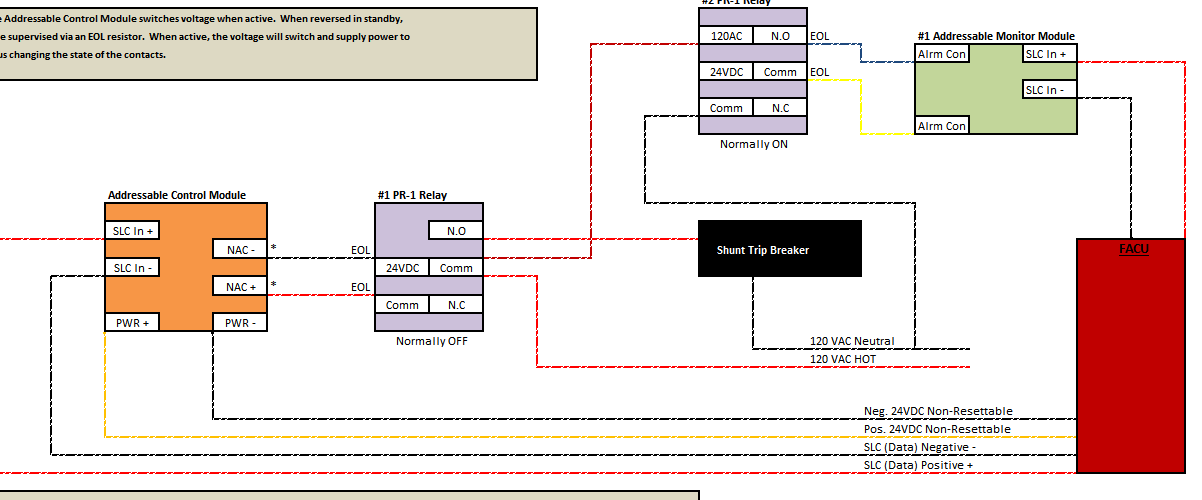
Elevator Shunt Trip Wiring Diagram

The diagram above illustrates two concepts for interfacing a fire alarm system with elevator shunt-trip equipment.

The important concept is not the specific NOTIFIER part number. It is understanding where the emergency control interface occurs and how the fire alarm control pathway is supervised.

What Is an ECID?

ECID stands for Emergency Control Interface Device.

In practical fire alarm design, the ECID is the interface through which the fire alarm system performs the required emergency control function.

For an elevator power-shutdown application, the ECID may be an addressable fire alarm interface located appropriately for the controlled equipment, or the design may use a supervised fire alarm control circuit operating another listed interface relay.

Which device serves as the actual interface depends on the system architecture.

This distinction matters because moving the interface farther away from the addressable fire alarm module can create an additional field-wiring pathway that must be considered in the supervision design.

The Basic ECID Concept

A useful way to visualize the arrangement is:

FACU → Supervised Fire Alarm Pathway → ECID → Controlled Emergency Function

For an addressable fire alarm system, the signaling line circuit itself is supervised by the fire alarm control unit.

However, simply having an addressable module somewhere in the system does not automatically mean every conductor beyond that module is supervised.

That is the key issue this article addresses.

Method 1: Addressable Relay at the Elevator Interface

One approach is to locate an addressable relay module at the point where the fire alarm system interfaces with the elevator power-shutdown control equipment.

The original example used a NOTIFIER FRM-1 addressable relay module.

The FRM-1 communicates with the compatible fire alarm control panel over the SLC and provides isolated Form-C relay contacts for controlling external equipment.

Conceptually:

FACU → Supervised SLC → Addressable Relay at Interface → Shunt-Trip Control Equipment

Locating the addressable interface at the controlled equipment can minimize the amount of unsupervised control wiring between the fire alarm interface and the equipment being controlled.

Important distinction: The FRM-1's addressable SLC connection is supervised by the fire alarm system, but its dry relay contacts do not magically supervise whatever external circuit is connected to those contacts. The complete interface must still be evaluated according to the approved design and applicable supervision requirements.

NOTIFIER FRM-1 Relay Module

The FRM-1 is an addressable relay module that allows a compatible NOTIFIER fire alarm control panel to operate dry relay contacts by command.

It provides two isolated Form-C contact sets that operate together.

This makes the FRM-1 useful for many fire alarm emergency-control interfaces where dry contacts are appropriate.

But there is an important limitation:

The FRM-1 is a relay module, not a universal power-control device.

The circuit being switched must remain within the manufacturer's listed contact ratings for the specific:

  • Voltage
  • Current
  • AC or DC application
  • Resistive or inductive load
  • Coded or non-coded operation where applicable

Never choose an interface relay based solely on its largest advertised ampere rating.

Why Relay Contact Ratings Matter

Relay contacts are not rated identically for every electrical load.

A contact capable of switching one current at a low-voltage resistive load may have a significantly different rating when switching an inductive load or a different voltage.

Shunt-trip coils and other control equipment can present electrical characteristics that must be checked against the relay manufacturer's published ratings.

Do not assume: A relay marked for a particular maximum current is automatically suitable for every shunt-trip circuit below that current. Verify the actual voltage, current and load type against the manufacturer's listed contact ratings.

What If the Fire Alarm Relay Cannot Directly Control the Load?

If the fire alarm relay contacts are not suitable for the circuit being controlled, the design can use an appropriately rated listed interface relay.

The fire alarm system then controls the interface relay rather than attempting to switch the external control load directly.

Conceptually:

FACU → Supervised Control Module → Interface Relay → Shunt-Trip Control Equipment

This is where the supervision design becomes especially important.

Method 2: FCM-1 With an External Interface Relay

The second arrangement in the original diagram uses a NOTIFIER FCM-1 addressable control module to operate an external interface relay.

This is fundamentally different from using an FRM-1.

The FRM-1 provides addressable dry relay contacts.

The FCM-1 provides a supervised control output designed to monitor the wiring connected to its output circuit.

NOTIFIER documentation describes the FCM-1 as capable of supervising its output wiring and reporting conditions such as normal, open and short to the fire alarm control system.

That capability is why a supervised control-module arrangement can be useful when an external interface relay must be located away from the addressable module.

Why Use an External Interface Relay?

An external interface relay may be necessary when:

  • The controlled voltage exceeds the appropriate rating of the fire alarm relay contacts
  • The controlled current exceeds the appropriate contact rating
  • The load characteristics are not suitable for the addressable relay
  • The project design requires a different listed interface
  • A supervised control circuit must extend from the fire alarm module to the final interface

The interface relay must itself be properly selected for the electrical characteristics of the controlled circuit.

The original diagram used a PR-1 style interface relay as an example. The exact relay used on a modern project should be selected from the approved equipment for that particular system rather than treating one legacy part number as universally required.

FRM-1 vs. FCM-1 for Elevator Shunt Trip

Feature FRM-1 FCM-1
Basic Device Type Addressable relay module Addressable control module
Typical Output Dry Form-C relay contacts Supervised control output
Output Wiring Supervision Dry contacts do not inherently supervise the external controlled circuit Designed to supervise connected control wiring when installed as specified
Useful Application Local dry-contact interface where appropriate Supervised pathway to an external interface/load where appropriate
Key Design Check Contact voltage/current/load rating Compatible external supply, supervised circuit and connected load

Why Module Location Matters

One of the easiest mistakes to make with emergency-control wiring is to focus entirely on the fire alarm panel and ignore where the actual interface device is located.

Consider two arrangements:

Arrangement A:

FACU → SLC → Addressable Interface → Controlled Equipment

Arrangement B:

FACU → SLC → Addressable Module → Long Field Control Circuit → Interface Relay → Controlled Equipment

Arrangement B introduces another pathway between the addressable module and the final interface.

That pathway cannot simply be ignored because the module itself has an address.

If the design requires supervision of that control pathway, the module and circuit architecture must provide that supervision.

What Wiring Is Actually Supervised?

This is the question every technician should ask when looking at an elevator shunt-trip interface.

Do not stop at:

"The module is addressable, so it's supervised."

Instead ask:

  • Is the SLC supervised?
  • Where is the emergency-control interface located?
  • Is there additional wiring between the addressable module and that interface?
  • Is that additional wiring supervised where required?
  • Is external control power monitored where required?
  • Would an open conductor prevent the required emergency function without creating a trouble indication?

Those questions expose the difference between an addressable device and a completely supervised emergency-control interface.

Supervising Shunt-Trip Operating Power

The control pathway is only part of the design.

The shunt-trip mechanism also needs the electrical power necessary to perform its required function.

If that operating power disappears, the fire alarm control relay could function perfectly while the elevator power-shutdown mechanism fails to operate.

Where required by the applicable design and code, loss of power necessary for the emergency control function must therefore be monitored so the impairment does not remain hidden.

The exact method depends on the shunt-trip equipment, control-power source and approved fire alarm design.

Do Not Confuse Control Power With Elevator Motor Power

The fire alarm system normally interfaces with the control side of the elevator power-shutdown equipment.

It is not routing the elevator motor feeder through an ordinary addressable fire alarm module.

The fire alarm interface operates the approved shunt-trip or disconnecting mechanism, which then performs the required power-disconnection function.

This distinction is important both electrically and from an equipment-listing standpoint.

Normally Open or Normally Closed?

There is no responsible universal answer that says every elevator shunt-trip interface should simply use the normally open or normally closed contacts of a relay.

The correct contact arrangement depends on:

  • The shunt-trip equipment
  • The control voltage
  • The approved sequence
  • The supervision method
  • The interface relay
  • The required normal and activated states
  • The equipment manufacturer's instructions

Follow the approved wiring diagram rather than selecting NO or NC based on habit.

Do Not Use the SLC as Proof That Everything Is Supervised

This deserves repeating because it is a common misunderstanding.

An addressable module being supervised on the SLC proves that the fire alarm control unit can communicate with that module.

It does not automatically prove that every conductor, relay coil, external power supply, or controlled circuit beyond the module is supervised.

Each part of the emergency-control interface must be evaluated according to what happens if that portion of the circuit opens, shorts, loses power or otherwise becomes impaired.

Common Elevator Shunt Trip Interface Mistakes

  • Using a relay without checking its actual contact rating.
  • Assuming an addressable relay supervises wiring connected to its dry contacts.
  • Installing the addressable module far from the final interface without evaluating the intervening wiring.
  • Confusing an FRM-1 relay module with an FCM-1 supervised control module.
  • Failing to monitor power required to perform the shutdown function where required.
  • Routing loads through fire alarm contacts that are not listed or rated for the application.
  • Assuming NO or NC contacts are universally correct.
  • Using legacy part numbers without checking current product documentation and compatibility.
  • Testing only the fire alarm module rather than the complete emergency-control function.

Testing the Elevator Shunt Trip Interface

Testing should verify more than whether the addressable module changes state.

The complete test should be coordinated with the elevator contractor and other responsible parties and should verify the approved sequence from initiating condition through the final controlled function.

Depending on the installation, this can include:

  • Correct fire alarm input
  • Correct system programming
  • Addressable module operation
  • Supervision of the applicable control pathway
  • External interface relay operation
  • Availability and monitoring of required control power
  • Operation of the approved elevator shutdown interface
  • Correct trouble indication when a supervised pathway is intentionally opened during testing
  • Proper restoration after the test
Testing Warning: Never intentionally interrupt elevator power simply to prove a fire alarm output without proper coordination. Elevator shutdown testing should be performed as an integrated test with the appropriate elevator, electrical, fire alarm and building personnel involved.

Frequently Asked Questions

What is an ECID in a fire alarm system?

ECID stands for Emergency Control Interface Device. It is the interface through which the fire alarm system performs an emergency control function such as an approved elevator power-shutdown operation.

Can an FRM-1 be used for elevator shunt trip?

An FRM-1 provides addressable dry relay contacts and may be suitable for an approved emergency-control interface when its application, contact ratings, location, supervision arrangement and equipment compatibility satisfy the project requirements. It should not be treated as a universal shunt-trip solution.

What is the difference between an FRM-1 and FCM-1?

The FRM-1 is primarily an addressable relay module providing Form-C dry contacts. The FCM-1 is an addressable control module capable of supervising its connected output wiring when installed in accordance with the manufacturer's instructions.

Does an addressable relay automatically supervise the shunt-trip circuit?

No. The fire alarm system supervises communication with the addressable module, but dry relay contacts do not automatically supervise all external wiring connected beyond those contacts.

Why would I use an FCM-1 with an interface relay?

A supervised control module can be useful where the fire alarm system must supervise the control wiring extending to an external interface relay. The external relay can then be selected for the electrical characteristics of the controlled circuit.

Can I use any 10-amp relay for elevator shunt trip?

No. Relay suitability depends on more than a single ampere rating. Verify voltage, AC or DC operation, load type, contact rating, listing, control characteristics and compatibility with the approved design.

Does the fire alarm relay carry elevator motor power?

Normally, no. The fire alarm system interfaces with the control circuitry for the approved elevator power-disconnection equipment. Elevator motor power is not normally routed through an ordinary addressable fire alarm relay.

Related Elevator Fire Alarm Guides

Final Thoughts

The most important concept in elevator shunt-trip interface wiring is understanding exactly where the emergency control interface occurs.

If an addressable relay is located at the final interface, the supervised SLC brings the fire alarm system directly to that point, but the dry contacts themselves do not automatically supervise the external circuit.

If an external interface relay must be located beyond the addressable device, a supervised control-module arrangement may be appropriate so the wiring to that interface can be monitored.

In either case, the designer must verify the relay ratings, control voltage, supervision requirements, equipment listings and approved elevator shutdown sequence.

Don't ask only, "Is the module supervised?" Ask, "Is the entire required control pathway supervised to the point where the emergency function is actually performed?"

Technical Disclaimer: This article is intended for qualified fire alarm and life-safety professionals. Always follow the currently adopted codes and standards, approved construction documents, equipment listings, manufacturer instructions, electrical-safety requirements and AHJ requirements for the specific installation.