Showing posts with label nicet. Show all posts

Friday, January 16, 2026

NICET Study Material: Proven Practice Exams for Faster Certification

If you work in the fire alarm, electrical, or low voltage design and installation industry, you already know what’s at stake: tighter specs, stricter inspections, and more projects that require documented competency. That’s exactly why our NICET Study Material has become a must-have for technicians, designers, inspectors, and project leads who want to level up and pass the NICET exam with confidence.

This guide breaks down what makes NICET preparation tough, what the best study tools include, and how professionally developed practice exams can help you pass sooner—and advance your career faster.


What Is NICET and Why Certification Matters

Fire alarm technician studying NICET study material with code books and practice exam notes
Fire alarm technician preparing for NICET certification using structured study material and practice exams.


NICET certification is a widely recognized credential used across fire protection and special systems. For many roles in fire alarm systems, electrical testing, and low voltage work, NICET can be a key requirement for certain employers, contracts, or project specifications. In plain terms, it proves you know your stuff—and can apply it under pressure.

Overview of NICET Certification Levels

NICET certifications commonly span Levels I through IV. Lower levels focus on fundamentals and terminology. Higher levels lean into real-world judgment, system-level thinking, advanced code application, and responsibility tied to design oversight and project management.

Industries That Rely on NICET Credentials

  • Educational and Higher Learning
  • Electrical power testing and maintenance
  • Low voltage, security, and communications systems
  • Government, municipal, and large institutional projects

Why NICET Exams Are Challenging for Technicians

NICET exams are challenging because they test more than basic familiarity with the code. They measure how quickly and accurately you can find, understand, and apply code requirements. Even seasoned field professionals can struggle when questions require careful interpretation and fast navigation through reference materials.


Technician taking NICET computer-based certification exam in a professional testing environment
Technician completing a NICET computer-based certification exam in a controlled testing environment.

Open-Book Exam Misconceptions

“Open-book” sounds like a free pass, but it can be the exact opposite. Candidates often waste time flipping pages, hunting for terms, or second-guessing where a specific requirement lives. Without practice, the book becomes a distraction instead of a tool. Learn to remember chapters and utilize the Index and Glossary to your advantage! 

Code Navigation vs Memorization

Success comes from knowing how to locate requirements quickly, interpret what they mean, and apply them to the scenario in the question. That’s why solid NICET Study Material that teaches both content and navigation are so effective. 


Why High-Quality NICET Study Material Makes the Difference

Random studying feels productive—until test day. The best study approach is structured, measured, and based on realistic practice. Quality prep tools act like a roadmap: they show you what matters most, how it’s tested, and where you’re losing points.

Structured Learning vs Guesswork

Professionally made study materials help you focus on:

  • Commonly tested topics and job tasks
  • Frequently used code references
  • Question styles that match real exam logic
  • “Gotchas” that cause incorrect answers (and how to avoid them)

Confidence, Speed, and Accuracy

When you’ve already seen the format, practiced the timing, and learned where to find answers fast, your confidence goes up—and your stress goes down. Practice exams also help you avoid the classic exam-day failure: running out of time.


Types of NICET Study Material Available

Practice Exams and Simulated Tests

Practice exams are the closest thing to “training for game day.” Strong practice tools are written to mimic the difficulty and pacing of the real exam, while also teaching you how to interpret questions and find the supporting references quickly.

Study Guides and Code Breakdown Resources

Good guides don’t just give answers—they explain why an answer is correct and where the supporting requirement comes from. That helps you learn the intent behind the rules, which matters when questions are scenario-based.

Online vs Printed Study Material

  • Online platforms: progress tracking, timed quizzes, instant scoring, frequent updates
  • Printed guides: easy jobsite review, offline access, quick reference notes

The most effective programs often combine both formats.


How Companies Create Effective NICET Study Material

The best vendors don’t toss together generic questions. They build material around real job tasks, code navigation habits, and exam-style logic. That’s why company-created resources—when done right—often outperform “free” random study lists.

Industry SME Involvement

High-quality study products are typically written or reviewed by subject matter experts who understand real-world design, installation, inspection, and troubleshooting challenges in fire alarm, electrical testing, and low voltage systems.

Alignment With Real NICET Exam Style

Strong prep materials match how the exam actually feels:

  • Scenario-based wording
  • Reference-driven questions
  • Distractor answers that look “almost right”
  • Time pressure similar to the real testing environment

Benefits of Using Professionally Developed Practice Exams

Identifying Knowledge Gaps

Practice exams quickly reveal where you’re weak—maybe it’s calculations, terminology, code navigation, inspection/testing steps, or system design scenarios. Once you know your gaps, your study time becomes efficient instead of endless.

Improving Time Management

Many candidates fail not because they don’t know the content—but because they can’t answer fast enough. Timed practice tests teach pacing and help you build a repeatable strategy: answer what you know first, mark the rest, then return with references.


Choosing the Right NICET Study Material for Your Trade

Fire Alarm Systems

Look for material that emphasizes:

  • Code navigation speed
  • Device placement and circuit concepts
  • Inspection/testing documentation logic
  • Scenario-based questions that mirror field decisions

Electrical Power Testing

Strong resources focus on:

  • Safety and best practices
  • Testing procedures and interpretation
  • Equipment fundamentals and measurement concepts

Low Voltage & Special Systems

Effective prep covers integrated systems thinking, signaling basics, communications concepts, and the installation/design habits used on modern projects.


Common Mistakes to Avoid When Studying for NICET

Relying Only on Codebooks

Codebooks are essential references, but they aren’t a study plan. Without a structured approach, it’s easy to spend hours reading and still miss what the exam actually tests.

Skipping Practice Exams

Reading alone doesn’t build exam readiness. Practice exams help you develop timing, accuracy, and confidence—three things you can’t fake on test day.


FAQs About NICET Study Material

1) Is NICET Study Material really necessary for open-book exams?

Yes. Open-book exams still require speed and accuracy. The right materials teach you how to find information quickly and apply it correctly under time pressure.

2) Are practice exams similar to the real NICET exam?

Well-built practice exams are designed to mirror real exam logic and difficulty, helping you get comfortable with the format before test day.

3) Can NICET Study Material help with higher-level exams?

Absolutely. As levels increase, questions become more scenario-based and responsibility-driven, making structured study and realistic practice even more important.

4) How long should I study before taking the NICET exam?

Many working professionals prepare over 4–8 weeks, depending on experience, level, and how consistently they practice.

5) Is online or printed study material better?

Both can work. Online tools are great for tracking and quizzes, while printed guides are handy for field-friendly review. Many candidates use a mix of both.

6) Do companies update NICET Study Material regularly?

Reputable providers typically update content to reflect code cycles, exam focus shifts, and student feedback.


Conclusion: Invest in the Right Tools, Pass With Confidence

In the fire alarm, electrical, and low voltage world, certification can open doors—better roles, better projects, and better pay. The right NICET Study Material turns studying from a grind into a system: learn what matters, practice how it’s tested, and walk into the exam prepared.

If you’re looking for trustworthy study tools and realistic practice exams built by industry pros, start with a provider that focuses on your exact NICET track and offers exam-style practice you can measure.

For additional background on NICET as a credentialing organization, you can reference the official NICET website here: NICET (Official Site).

Thursday, February 29, 2024

Smoke Control for Dummies

FIRE ALARMS ONLINE • CODE GUIDE

Smoke Control Systems Explained (IBC 2021 + NFPA 92 Guide for Fire Alarm Professionals)

Do you struggle to understand smoke control for fire alarm systems? No need to stress out, because you are not alone. Let’s break it down so it is easier to digest.

Smoke control is a vital aspect of fire protection engineering that aims to prevent the spread of smoke and toxic gases in buildings during a fire. Smoke control systems use various strategies, such as mechanical ventilation, pressurization, and compartmentation, to limit the movement of smoke and protect the occupants and property from its harmful effects. In this blog post, you will learn about the principles, design, and applications of smoke control systems, as well as the relevant codes and standards that govern their performance. You will also find some useful resources and references to help you further explore this topic. Whether you are a fire protection engineer, a building owner, an installer, or a curious reader, this blog post will provide you with valuable insights into the science and practice of smoke control.

Fire alarm systems are essential for the activation and operation of smoke control systems. Fire alarm systems can detect the presence of fire and smoke, alert the occupants and the fire department, and initiate the appropriate smoke control actions. Fire alarm systems can also monitor the status and performance of smoke control systems and provide feedback and control signals to the building management system. Fire alarm systems should be listed, compatible, and integrated with the smoke control system to ensure coordinated and effective response to fire emergencies.

👉 Want to master fire alarm system design? Check out our complete Fire Alarm Requirements Guide by Occupancy.

Smoke control systems are complex and require careful design, installation, and maintenance. Smoke control systems should be based on a thorough analysis of the fire hazards, the building characteristics, the occupant needs, and the fire department operations. This approach is referred to as a smoke control report or rational analysis and is required to be completed by a registered fire protection engineer (FPE) per the International Building Code 2021 Section 909.4. The rational analysis or smoke control report will cover which type of smoke control system will be employed (passive vs. mechanical), which smoke control method will be utilized (pressure, exhaust, or air flow), construction methods, sequence of operation and inspection and testing procedures. There are other items covered within the report such as, but not limited to, stack effect, temperature effect of fire, wind effect, climate and duration of operation.

Smoke Control Quick Breakdown

  • Required by IBC Section 909 for specific building types and conditions
  • Designed using a Rational Analysis prepared by a registered FPE
  • Includes Passive and Mechanical Smoke Control Systems
  • Integrated with Fire Alarm Systems for activation, supervision, and monitoring
  • Requires verification or positive status for mechanical systems
  • Must be tested, commissioned, and approved before occupancy

What Codes and Standards Dictate Smoke Control Systems?


Smoke control systems are required and regulated by codes and standards that specify the performance requirements, design criteria, installation methods, and testing procedures for different types of buildings and occupancies. Some of the codes and standards that address smoke control systems are as follows:
  • 2021 International Building Code (IBC) Chapter 9: Fire Protection and Life Safety Systems
  • ASHRAE Handbook of Smoke Control Engineering
  • NFPA 92: Standard for Smoke Control Systems
  • NFPA 101: Life Safety Code
  • NFPA 72: National Fire Alarm and Signaling Code
  • Underwriters Laboratories, UUKL, Smoke Control Equipment (ANSI/UL 864 units for fire protective signaling systems)

Where are Smoke Control Systems Required per Code?

  • Atriums (three stories or more) within covered malls - IBC 2021 Section 402.7.2.
  • High-Rise Buildings - IBC 2021 Section 403.4.7.
  • Atriums (three stories or more) - IBC 2021 Section 404.5.
  • Underground Buildings - IBC 2021 Section 405.5.
  • Mechanical Access Enclosed Parking Garage - IBC 2021 Section 406.6.4.2.
  • Windowless Buildings Group I-3 - IBC 2021 Section 408.9
  • Large Stages (Greater than 1,000 sq' in Area or 50' in Height) - IBC 2021 Section 410.2.7.
NICET PRACTICE SPOTLIGHT
🔥 Practice Question

Which of the following occupancies requires a smoke control system per IBC 2021?

A. Single-story warehouse
B. Atrium connecting 3 or more floors
C. Small office tenant improvement
D. Open parking garage

Answer: B

👉 Want 500+ real NICET-style questions like this? Visit FireAlarmsOnline.com
Underground building and parking garage smoke control system example
Smoke Control Underground Structures

Passive vs. Mechanical Smoke Control Systems

Passive Smoke Control Systems

Passive smoke control systems rely on the buoyancy and pressure differences of smoke and air to create ventilation openings that allow smoke to escape and fresh air to enter. Examples of natural smoke control systems are automatic opening vents (AOVs), atrium exhausts, opposed airflow, and smoke reservoirs.

  • Openings are protected by automatic closing equipment or devices.
    • Fire Dampers and Combination Fire Smoke Dampers
    • Fire Rated Doors with Magnetic Hold Open Devices (Door Holders)
  • Activation - Consult the Approved Rational Analysis / Smoke Control Report.
    • Smoke Detectors / Heat Detectors located at fire rated doors and combination fire smoke dampers.
    • Duct Smoke Detectors located at HVAC units for shutdown and combination fire smoke dampers.
  • Verification NOT required.
    • Positive status of fan shutdown, door closure or damper activation is not required per IBC 2021 Section 909.12.1. Consult the rational analysis as it may supersede this code section.
  • Wiring
    • In addition to the requirements of NFPA 70, all wiring regardless of voltage shall be fully enclosed within a continuous raceway.
🔥 NICET Tip: Smoke detector spacing is one of the most tested topics on NICET exams. Learn beam and spot detector spacing here.

Mechanical Smoke Control Systems

Mechanical smoke control systems use fans, dampers, ducts, and other devices to create pressure differences and airflow patterns that control the direction and speed of smoke movement. Examples of mechanical smoke control systems are pressurization method, exhaust method, and air flow method systems.

Pressurization Method

  • Pressurization Method - IBC 2021 Section 909.6. This approach utilizes pressure differences across smoke barriers to maintain a tenable environment zones adjacent to the smoke control zone of origin.
    • Per IBC 2021 Section 909.6.1, the minimum pressure across the smoke barriers is 0.05" water gauge.
    • The maximum pressure differential is dependent upon the opening force of exit doors. Per IBC 2021 Section 1010.1.3 #2, the door shall not require more than 30 pounds of force to set in motion and 15 pounds to fully open.
    • Required to have complete automatic control 2021 IBC Section 909.12.3.1.
    • In addition to the requirements of NFPA 70, all wiring regardless of voltage shall be fully enclosed within a continuous raceway.
Smoke control pressurization method detail for stairwell and smoke zone protection
Smoke Control Pressurization Method Detail
Stairwell pressurization smoke control system example
Smoke Control Stairwell Pressurization

Exhaust Method

  • Exhaust Method - IBC 2021 Section 909.8. Where approved by the AHJ, the exhaust method may be utilized in large areas such as atriums or malls. Large smoke exhaust fans are utilized to evacuate smoke from the area. Makeup air (MAU) fans, automatic windows or doors may be used to replace air removed from the space by process of the smoke exhaust fan. When the smoke control exhaust method is utilized, the system must keep the smoke layer at least six feet above the highest level meant for egress within the smoke zone. Smoke Control Systems utilizing the exhaust method shall be designed in accordance with NFPA 92.
    • Required to have complete automatic control 2021 IBC Section 909.12.3.1.
    • In addition to the requirements of NFPA 70, all wiring regardless of voltage shall be fully enclosed within a continuous raceway.
Smoke control exhaust method detail for atriums and large open spaces
Smoke Control Exhaust Method Detail

Atrium smoke exhaust system example for smoke control
Smoke Control Exhaust Method Atrium

Air Flow Method

  • Air Flow Method - IBC 2021 Section 909.7. Where approved by the AHJ, the air flow method is used for facilities with smoke migration through openings that are in the permanently open position. Airflow shall be directed to limit smoke migration from the zone. Airflow shall not exceed 200 feet per minute. Smoke Control Systems utilizing the air flow method shall be designed in accordance with NFPA 92.
  • This method shall not be employed where either the quantity of air or the velocity of the airflow will adversely affect other portions of the smoke control system, intensify the fire, disrupt smoke plume dynamics or interfere with exiting. Airflow towards the fire shall not exceed 200 feet per minute. Where the calculated airflow exceeds this limit, the airflow method shall NOT be used. 909.7.1.
    • Required to have complete automatic control 2021 IBC Section 909.12.3.1.
    • In addition to the requirements of NFPA 70, all wiring regardless of voltage shall be fully enclosed within a continuous raceway.
Smoke control air flow method detail for open smoke zones
Smoke Control Airflow Method Detail

Duration of Operation


2021 IBC Section 909.4.6 states that all portions of active or engineered smoke control systems shall be capable of continued operation after detection of the fire event for a period of not less than either 20 minutes or 1.5 times the calculated egress time, whichever is greater.

What is Verification or Positive Status?


Smoke control equipment utilized in a mechanical smoke control system will be required to comply with IBC 2021 Section 909.12.1 "Verification". This is also known as positive status. This is the process of utilizing fire alarm monitoring modules to supervise the activation of fans, dampers and doors in a smoke control event. The fire alarm monitor modules can be connected to variable frequency drives (VFDs), end switches, pressure differential switches, and current switches. These components provide contact closure to trip the associated fire alarm monitoring module to prove the fan, damper, or doors activated as intended per the approved rational analysis or smoke control report.
Smoke control verification and positive status equipment for fire alarm monitoring
Smoke Control Positive Status Equipment

Examples of how positive status for smoke control system can be wired to a fire alarm monitoring module. In these examples, a Notifier FDM-1 addressable dual monitor module is used to show how to wire up a damper actuator end switch for normally open and normally closed conditions.
Smoke damper positive status wiring detail for normally open condition
Fire Smoke Damper Status Monitoring Open Detail
Smoke damper positive status wiring detail for normally closed condition
Fire Smoke Damper Status Monitoring Closed Detail

There is more to smoke control verification.


Another requirement for verification is a preprogrammed weekly self test sequence that shall report abnormal conditions audibly, visually, and by printed report. The pre-programmed weekly test shall operate ALL devices equipment and components used for the smoke control system.

Exception:
  • Where verification of individual components tested through the preprogrammed weekly testing sequence will interfere with, and produce unwanted effects to, normal building operation, such individual components are permitted to be bypassed from the preprogrammed weekly testing, when approved by the AHJ and in accordance with BOTH of the following:
  1. Where the operation of components is bypassed from the preprogrammed weekly test, presence of power downstream of all disconnects shall be verified weekly by a listed control unit.
  2. Testing of all components bypassed from the preprogrammed weekly test shall be in accordance with section 909.20.6 of the International Fire Code IFC.

UL listed smoke control printer for weekly test reports
Example of a UL Listed Smoke Control Printer for Weekly Testing Reports

Fire Fighter's Smoke Control Panel


A fire fighter's smoke control panel for first responder purposes ONLY shall be provided and include manual control or override of automatic control for mechanical smoke control systems. If the facility is a high-rise structure or equipped with smoke protected assembly seating, the fire fighter's smoke control panel shall be installed with the fire command center (FCC). For all other buildings that may require a smoke control system, the fire fighter's smoke control panel shall be installed in an area approved by the AHJ adjacent to the fire alarm control panel. 2021 IBC Section 909.16.

Smoke Control Indication LEDs


All fans, dampers and other operating equipment shall be depicted on the fire fighter's smoke control panel along with clear indication of the airflow. Status indicators shall be included for all smoke control equipment annunciated by fan, damper and or zone. 2021 IBC Section 909.16.1.
  1. Fans, Dampers and Other Operating Equipment NORMAL status = WHITE
  2. Fans, Dampers and Other Operating Equipment OFF or CLOSED status = RED
  3. Fans, Dampers and Other Operating Equipment ON or OPEN status = GREEN
  4. Fans, Dampers and Other Operating Equipment FAULT status = AMBER/YELLOW

Smoke Control Switches


The following switches shall be provided on the smoke control panel to provide control capability over the complete smoke control equipment with the building: 2021 IBC Section 909.16.2
  • ON-AUTO-OFF control over each individual piece of operating smoke control equipment that can be controlled from other sources within the building. This can include: stair pressure fans, smoke exhaust fans, supply fans, return fans, exhaust fans, elevator shaft fans, and other operating equipment used or intended for smoke control purposes.
Smoke control on-auto-off fan switch
Smoke Control On-Auto-Off FAN Switch
  • ON-AUTO-OFF control over individual dampers relating to smoke control and that are controlled from other sources within the building.
Smoke control on-auto-off damper switch
Smoke Control On-Auto-Off DAMPER Switch
  • ON-OFF or OPEN-CLOSED control over smoke control and other critical equipment associated with a fire or smoke emergency and that can only be controlled from the fire fighters smoke control panel.
Smoke control on-off door switch
Smoke Control On-Off DOOR Switch

Exceptions:
  1. For complex systems (where approved), controls and indicators can be combined to control and indicate all components of a single smoke zone as a single unit. This allows for one switch to control multiple doors, dampers or fans within a single smoke zone. Example: Five dampers on the 10th floor that are all required to close upon smoke mode activation could be controlled and indicated on a single switch with LEDs on the 10th floor of the fire fighter's smoke control panel. 2021 IBC Section 909.16.2

The ON-OFF and OPEN-CLOSE switches shall have the highest priority over any control point within the building. Once automatic or manual control has been initiated from the fire fighter's smoke control panel, any other point in the building shall NOT contradict the control action. The only exception is power disconnects required by NFPA 70.

The AUTO position on three-position switches shall allow automatic or manual control action from other control points within the building. The AUTO position is the normal nonemergency position.

Fire Fighter's Smoke Control Example


Fire fighter smoke control panel example with switches and status indicators
Fire Fighter's Smoke Control Panel

Smoke Control System Response Time


Per 2021 IBC Section 909.17, upon receipt of an alarm condition at the fire alarm control panel fans, dampers, and automatic doors shall have achieved their proper operating state and the final status shall be indicated at the smoke control panel within 90 seconds.

Power Requirements

  • Standby Power Requirements per section 2702.2.17 of the 2021 IBC states that standby power shall be required for smoke control systems per sections 404.7, 909.20.7.2, and 909.21.5.
  • Per section 909.12.1 the smoke control system shall monitor for the presence of power downstream of all disconnects. This will require a monitor module as well as an isolation relay (PR-1 or MR-101) at each power source. Make sure to pay attention to DAMPERS. A lot of the systems today will have a light switch adjacent to the damper actuator for the purpose of dropping power to the unit for service. If this is the case, you will need a monitor module and relay at each of these locations. Pay attention to this when bidding a project as this could potentially add quite a few more modules than you may have accounted for.

How are smoke control systems commissioned and tested?


Per the 2021 International Building Code Section 909.3, smoke control systems shall undergo special inspections and testing in place to verify the proper commissioning of the smoke control design in its final installed condition. As noted above, the rational analysis or smoke control report is required to include procedures that shall be used during the testing and commissioning process.
  • Per the 2021 IBC, Section 1705.19, Smoke Control Systems shall be tested by a special inspector.
    • As defined by the 2021 IBC Definitions, a special inspector is a qualified person employed or retained by an approved agency and approved by the building official as having the competence necessary to inspect a particular type of construction requiring special inspection.
  • Per the 2021 IBC, Section 1705.19.1, the Smoke Control Testing Procedure shall include:
  1. During erection of ductwork and prior to concealment for the purpose of leakage testing and recording of device and equipment locations. This includes but not limited to fans, dampers, smoke detectors, waterflow switches, and verification equipment as outlined above.
  2. Prior to occupancy and after sufficient completion for the purpose of pressure differential testing, air flow measurements and detection and control verification.
  • Per 2021 IBC, Section 1705.19.2, approved agencies for smoke control testing shall have expertise in fire protection engineering, mechanical engineering, and certification in air balancing.

Reports

  • Per 2021 IBC Section 909.18.8.3, A complete report of testing shall be prepared by the approved agency. The report shall include identification of all devices by manufacturer, nameplate data, design values, measured values, and identification tags. The report shall be reviewed by the responsible registered design professional and, when satisfied that the design intent has been achieved, the responsible registered design professional shall sign seal and date the report.
  • A copy of the final report shall be given to the fire code official along with an identical copy to be filed in an approved location at the facility. 2021 IBC 909.18.3.1.
  • Charts drawings and other documents identifying and locating each component of the smoke control system as well as describing its proper function and maintenance requirements shall be maintained on file at the building and accompany the report required by section 909.18.8.3. Devices shall have an approved identifying tag on them consistent with the other required documentation and shall be dated indicating the last time they were successfully tested and by whom.

System Acceptance

  • 2021 IBC Section 909.19 states, buildings that are required by this code to employ a smoke control system shall not be issued a certificate of occupancy until such time that the AHJ determines the provisions of chapter 909 have been fully complied with and that the fire department has received ample instruction on the operation both automatic and manual operation of the smoke control system. In addition, a written maintenance program complying with the requirements of section 909.20.1 of the International Fire Code (IFC) has been submitted and approved by the AHJ.

Plan on at least three inspections to commission a smoke control system.

  • Pre-Test the system. Just like a fire alarm system, the sequence and equipment must be ran through prior to calling out the AHJ. The pre-test shall be conducted once all of the power is present, doors are installed, and all fire alarm/smoke control components are in place and programmed per the rational analysis, sequence of operations and approved documentation. Verify all indicators on the fire fighter's smoke control panel as well as manual and automatic operation.
  • Test with the third-party fire protection firm. Please note this can be the same firm that performed the rational analysis pending they have sufficient training and expertise in testing and commissioning smoke control systems. Depending on the individual conducting the third-party test you may have different requirements. However, you should still run through everything you tested during the pre-test as well as the pre-programmed weekly self-test. At the end of this test, the third party testing firm will issue a report per section 909.18.8.3 and give it to the Fire Code Official.
  • Final inspection with the AHJ / Fire Code Official. Once the third-party testing firm has issued their report, the AHJ will want to run through a final test. It is up to the AHJ on what will be tested. In my experience, some AHJs will trust the third-party testing firm and perform minimal testing to satisfy their needs. However, some AHJs will want to run through a complete test of all components. Keep this in mind when bidding projects as these tests can take quite a while depending on their complexity.

Frequently Asked Questions About Smoke Control Systems

What is a smoke control system?

A smoke control system is a life safety system designed to limit the movement of smoke during a fire. Depending on the building and design approach, it may use passive features, mechanical fans, dampers, doors, pressure relationships, or airflow methods to help maintain tenable conditions for occupant egress and fire department operations.

What is a smoke control rational analysis?

A smoke control rational analysis, sometimes called a smoke control report, is the engineering document that explains how the smoke control system is intended to function. It is typically prepared by a registered fire protection engineer and addresses the system type, method, sequence of operation, testing, environmental effects, and duration of operation.

What is verification or positive status in a smoke control system?

Verification, also known as positive status, is the process of proving that smoke control equipment such as fans, dampers, and doors actually reached their intended operating state during a smoke control event. This is commonly done using fire alarm monitor modules connected to end switches, current switches, pressure switches, or VFD status points.

When is a fire fighter’s smoke control panel required?

A fire fighter’s smoke control panel is required for mechanical smoke control systems so first responders can manually override or control the system. In high-rise buildings and smoke-protected assembly seating, it is typically installed in the fire command center. In other buildings, it is usually installed adjacent to the fire alarm control panel in an AHJ-approved location.

How are smoke control systems tested and commissioned?

Smoke control systems are tested through special inspection and commissioning procedures that verify pressure relationships, airflow, detection, controls, verification points, and overall sequence of operation. These tests are typically performed by approved agencies and reviewed by the design professional and AHJ before the building can receive occupancy approval.

Want more practical fire alarm code help like this? Browse more Fire Alarms Online articles for field-friendly breakdowns, code references, and NICET-style training content built for real-world installers, designers, estimators, and inspectors.

LEVEL UP YOUR FIRE ALARM GAME

🚀 Ready to Master Fire Alarm Systems?

Download our NICET Practice Exams, Fire Alarm Bluebeam Toolkits, and Design Guides used by professionals across the industry.

Visit FireAlarmsOnline.com

Friday, October 14, 2022

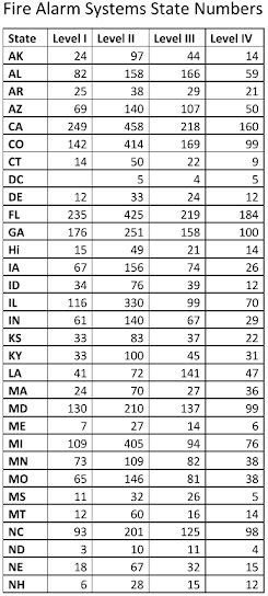
NICET FAS Certifications by State

If you are certified by the National Institute for Certification in Engineering Technologies (NICET) in Fire Alarm Systems (FAS), you may be interested to see how your state ranks up. The cart below has been provided to me by NICET to help show the country how you stack up. I was surprised to see which state came out on top in the most NICET FAS certified technicians. Its also great to see the tail number is up to 17,046 certifier individuals. Keep it up!


Monday, April 22, 2019

Fire Alarm Voltage Drop Calculator & NAC Calculation Guide

Fire Alarm Design Guide

Fire Alarm Voltage Drop Calculations: NAC Formulas, Methods & Examples

Learn how to calculate voltage drop on a fire alarm notification appliance circuit (NAC), including end-of-line and point-to-point methods, wire resistance, appliance current, minimum voltage and a complete worked example for fire alarm designers, technicians and NICET candidates.

Quick Answer: How Do You Calculate Fire Alarm Voltage Drop?

Fire alarm voltage drop is calculated using Ohm's Law. Determine the current flowing through the circuit and the resistance of the conductors, then multiply current by resistance.

Voltage Drop (V) = Current (A) × Resistance (Ω)

For a simplified end-of-line calculation, the total circuit current is applied to the conductor loop. For a point-to-point calculation, each wire segment is calculated individually using only the current that continues downstream through that segment.

Subtract the calculated voltage loss from the minimum NAC terminal voltage documented for the specific fire alarm control unit or power supply. The remaining voltage at every notification appliance must meet or exceed the appliance manufacturer's listed minimum operating voltage.

Why Fire Alarm NAC Voltage Drop Calculations Matter

Notification appliances can be wired correctly and still fail to operate properly if insufficient voltage reaches them during alarm conditions.

Voltage drop calculations help verify that horns, strobes, horn/strobes and other notification appliances receive enough voltage under the expected circuit load.

A proper calculation can also help determine:

  • How many notification appliances can be installed on a NAC
  • Whether a larger conductor size is required
  • Whether additional notification circuits or remote power supplies are necessary
  • The approximate voltage available at each appliance
  • Whether the circuit remains within the manufacturer's operating limits
  • Whether the circuit design is likely to perform correctly under alarm load
Important: Do not assume that 16 VDC is the universal minimum voltage for every 24-volt notification appliance. Many regulated 24 VDC appliances have historically been listed over ranges such as 16–33 VDC, but the actual minimum operating voltage must be taken from the data sheet and listing for the specific appliance being used.
Fire alarm NAC voltage drop explained with FACP, notification appliances, wire length, current and voltage drop formula
Fire alarm NAC voltage drop concept showing current flowing through multiple notification appliances. The voltage values shown in this infographic are conceptual examples only; use the verified worked calculation later in this article for the exact mathematical example.

What Information Is Needed for a Fire Alarm Voltage Drop Calculation?

Before starting the calculation, collect the actual design information for the circuit.

  • Minimum NAC terminal voltage: Use the minimum output voltage documented by the fire alarm control unit or notification power supply manufacturer for the applicable operating condition.
  • Notification appliance current: Use the listed current draw for the exact horn, strobe, candela, pattern or other selected setting.
  • Minimum appliance operating voltage: Confirm the listed operating voltage range for every connected appliance.
  • Actual wire length: Use the planned conductor routing rather than straight-line architectural distance.
  • Conductor resistance: Use the appropriate resistance value for the wire size, conductor material and applicable temperature assumptions.
  • Circuit topology: Confirm the Class, pathway arrangement, return path and manufacturer-specific circuit configuration.
  • Equipment compatibility: Confirm that the notification appliances, power supply and fire alarm control equipment are listed and compatible for the intended application.
Design Rule: Equipment listings and manufacturer instructions control. Always verify the adopted codes, project specifications, local amendments and AHJ requirements before finalizing a fire alarm voltage drop calculation.
NFPA 72 Documentation Note: Voltage-drop calculations are an important part of fire alarm system design documentation. Depending on the adopted edition and AHJ requirements, voltage-drop calculations for notification appliance circuits may be required as part of the system submittal package.

End-of-Line vs. Point-to-Point Fire Alarm Voltage Drop

Two commonly used calculation approaches are the end-of-line loaded method and the point-to-point method.

End-of-line versus point-to-point fire alarm NAC voltage drop calculation methods
End-of-line calculations apply the circuit load conservatively across the conductor path, while point-to-point calculations account for the current remaining after each notification appliance.
Method How It Works Advantages Limitations
End-of-Line / End-Line Loaded Applies the circuit load across the conductor path using a conservative end-loaded approach. Fast, simple and conservative. Can calculate more voltage loss than the circuit actually experiences because downstream segments do not carry the full original circuit current.
Point-to-Point Calculates each wire segment using the actual downstream current carried by that segment. More accurately represents the electrical behavior of the circuit. Requires accurate segment lengths, appliance locations and additional calculations.
Which method should you use? Use the calculation method required or accepted by the equipment manufacturer, design professional, project specifications and authority having jurisdiction. Point-to-point calculations can provide a more precise model, while end-line-loaded calculations are intentionally conservative.

Fire Alarm Voltage Drop Formula

The basic electrical relationship is Ohm's Law:

V = I × R

Where:

  • V = voltage drop in volts
  • I = current in amperes
  • R = conductor resistance in ohms

Conductor Resistance Formula

If conductor resistance is expressed in ohms per 1,000 feet:

Resistance (Ω) = Wire Length (ft) × Resistance per 1,000 ft ÷ 1,000

For a simplified two-conductor circuit calculation, remember that the current travels through both the outgoing and return conductors.

Do not double the distance automatically on every circuit configuration. The conductor path must reflect the actual circuit topology. Class A, Class B and manufacturer-specific arrangements can affect how circuit length is evaluated.

End-of-Line Voltage Drop Calculation

1
Add the notification appliance current. Total the worst-case listed current for every appliance on the NAC. Convert milliamperes to amperes before using Ohm's Law.

Example: 375 mA = 0.375 A
2
Determine the conductor path. Use the actual planned conductor routing. In the simplified two-conductor example below, the one-way segment lengths are added together and doubled to represent outgoing and return conductors.
3
Calculate conductor resistance. Multiply the conductor length by the appropriate wire resistance per foot, or divide by 1,000 when the conductor resistance is expressed in ohms per 1,000 feet.
4
Calculate the voltage drop. Multiply circuit current in amperes by conductor resistance in ohms.
5
Calculate the remaining voltage. Subtract the calculated voltage loss from the manufacturer's documented minimum NAC terminal voltage.
Remaining Voltage = Minimum NAC Terminal Voltage − Calculated Voltage Drop

Compare the remaining voltage with the listed minimum operating voltage of the connected notification appliances.

Worked Fire Alarm NAC Voltage Drop Example

The following example retains the original circuit values used in this Fire Alarms Online article while correcting the historical point-to-point calculation.

  • Example minimum NAC terminal voltage: 19.9 VDC
  • V1 current = 85 mA
  • V2 current = 75 mA
  • V3 current = 115 mA
  • V4 current = 100 mA
  • Total appliance current: 375 mA = 0.375 A
  • One-way conductor segments: 200 ft, 150 ft, 25 ft and 70 ft
  • Total one-way length: 445 ft
  • Simplified two-conductor loop length: 890 ft
  • Example #12 AWG stranded uncoated copper conductor resistance: 1.98 Ω per 1,000 ft
Important: The 19.9 VDC starting value is used only for this worked example. Do not assume 19.9 VDC, nominal 24 VDC or any other single voltage applies to every fire alarm system. Use the documented minimum NAC output voltage for the specific FACP or notification power supply being designed.

End-of-Line Method

First calculate the conductor resistance:

(890 ft ÷ 1,000) × 1.98 Ω = 1.7622 Ω

Next calculate the voltage drop:

0.375 A × 1.7622 Ω = 0.660825 V

Subtract the voltage drop from the example starting voltage:

19.9 V − 0.660825 V = 19.239175 VDC

The calculated voltage at the end of the simplified circuit is approximately:

19.239 VDC

That value must then be compared with the listed minimum operating voltage for the actual notification appliances.

Point-to-Point Method

The point-to-point method calculates voltage loss separately on every conductor segment using only the appliances located downstream of that segment.

Segment Loop Resistance Downstream Current Segment Drop Voltage After Segment
FACP to V1: 200 ft 400 ÷ 1,000 × 1.98 = 0.792 Ω 0.375 A 0.297 V 19.603 VDC
V1 to V2: 150 ft 300 ÷ 1,000 × 1.98 = 0.594 Ω 0.290 A 0.17226 V 19.43074 VDC
V2 to V3: 25 ft 50 ÷ 1,000 × 1.98 = 0.099 Ω 0.215 A 0.021285 V 19.409455 VDC
V3 to V4: 70 ft 140 ÷ 1,000 × 1.98 = 0.2772 Ω 0.100 A 0.02772 V 19.381735 VDC
Corrected Point-to-Point Result: The original historical version of this calculation accidentally used 0.200 A on the final conductor segment even though the only downstream appliance, V4, draws 0.100 A. The corrected voltage at V4 is approximately 19.382 VDC.

End-of-Line vs. Point-to-Point Result

End-of-Line: 19.239 VDC

Point-to-Point: 19.382 VDC

The point-to-point result is slightly higher because the current decreases as each appliance is passed. The end-of-line method conservatively applies a larger load across more of the conductor path.

Why You Should Not Start With Nominal 24 VDC

One of the most common fire alarm voltage drop mistakes is starting the calculation at a nominal system voltage such as 24 VDC without checking the manufacturer's documentation.

The actual minimum available NAC voltage can be affected by:

  • Battery operating voltage
  • Internal control-unit voltage losses
  • Power supply design
  • NAC circuitry
  • Operating conditions
  • Equipment listing

For design calculations, use the minimum NAC terminal voltage published by the manufacturer for the applicable equipment and operating condition.

How Wire Size Affects Fire Alarm Voltage Drop

Larger conductors have less resistance and therefore produce less voltage drop for the same circuit length and current.

For example, changing a long or heavily loaded NAC from a smaller conductor to a larger conductor can sometimes bring the circuit back within acceptable operating limits without adding another power supply.

However, larger wire is not automatically the best solution. Designers should evaluate:

  • Conductor cost
  • Raceway fill
  • Terminal limitations
  • Manufacturer requirements
  • NAC capacity
  • Number of circuits
  • Remote power supply locations
  • Future expansion

Does Candela Affect Fire Alarm Voltage Drop?

Yes. On many visual and audible/visual notification appliances, changing the candela setting changes the appliance current.

Higher candela settings frequently require more current. That additional current can increase voltage drop and reduce the number of appliances that can be installed on a circuit.

Always calculate the circuit using the current associated with the actual selected candela and operating setting.

Fire Alarm Voltage Drop and NAC Current Capacity Are Different

A circuit can pass the voltage drop calculation and still exceed the maximum current capacity of the notification appliance circuit.

Both conditions must be checked:

  • NAC current capacity: Is the total connected load within the rated output of the circuit?
  • Voltage drop: Is enough voltage available at every appliance?

A successful voltage drop calculation does not override a manufacturer's maximum circuit current rating.

Common Fire Alarm Voltage Drop Mistakes

  • Using nominal 24 VDC instead of the manufacturer's minimum NAC terminal voltage
  • Using the wrong current for the selected strobe candela or audible setting
  • Forgetting to convert milliamperes to amperes
  • Using straight-line distance instead of actual routed conductor length
  • Assuming 16 VDC is universally acceptable for every appliance
  • Using the full circuit current on every segment while calling the calculation point-to-point
  • Ignoring conductor temperature and resistance assumptions
  • Using resistance data for the wrong conductor size or material
  • Ignoring synchronization and equipment compatibility requirements
  • Exceeding NAC current capacity even though voltage drop passes
  • Rounding intermediate calculations too early
  • Failing to account for whips, risers, drops, service loops or other conductor length
  • Failing to coordinate the calculation with the actual installed routing

Fire Alarm Voltage Drop Frequently Asked Questions

What is the formula for fire alarm voltage drop?

The basic formula is Ohm's Law: voltage drop equals current in amperes multiplied by conductor resistance in ohms.

V Drop = I × R

What starting voltage should I use for a fire alarm NAC?

Use the minimum NAC output or terminal voltage specified by the manufacturer for the particular control unit or notification power supply and applicable operating condition. Do not automatically use nominal 24 VDC.

Is 16 VDC always the minimum fire alarm appliance voltage?

No. Some regulated 24 VDC notification appliances are listed for operation down to 16 VDC, but the correct minimum voltage is the value published for the exact appliance being installed.

Which voltage drop method is more accurate?

The point-to-point method generally models the actual circuit more accurately because current decreases after each appliance. The end-line-loaded method is more conservative because it assumes a greater load across the circuit.

Which voltage drop method should I use?

Use the method accepted or required by the equipment manufacturer, project specifications, design professional and authority having jurisdiction.

Do I need to double the fire alarm wire length?

For a simple two-conductor circuit calculation, both outgoing and return conductor resistance must be accounted for. However, do not blindly double architectural distance on every circuit. Calculate the actual conductor path based on the circuit configuration.

Does higher strobe candela increase voltage drop?

It often does because higher candela settings can increase appliance current. Use the manufacturer's listed current for the exact candela and operating setting.

Can a voltage drop calculation pass while the NAC is overloaded?

Yes. Voltage drop and circuit current capacity are separate design checks. The total connected appliance current must remain within the rated capacity of the NAC even when the available voltage is acceptable.

Is point-to-point always required?

Not necessarily. Both conservative end-line-loaded calculations and detailed point-to-point calculations are used in fire alarm design. Follow the requirements of the equipment manufacturer, project specifications and AHJ.

Does passing the voltage drop calculation guarantee compliance?

No. The system must also comply with equipment listings, compatibility requirements, current limits, synchronization requirements, conductor requirements, manufacturer instructions, adopted codes, approved plans, specifications and AHJ requirements.

Fire Alarm Voltage Drop Design Checklist

Before completing the circuit calculation, verify:

☐ Minimum NAC terminal voltage

☐ Exact notification appliance model

☐ Selected horn or audible setting

☐ Selected strobe candela

☐ Appliance current draw

☐ Minimum appliance operating voltage

☐ Total connected NAC current

☐ Actual conductor routing

☐ Conductor size

☐ Conductor material

☐ Conductor resistance

☐ Applicable temperature assumptions

☐ Circuit Class and topology

☐ Power supply compatibility

☐ Synchronization requirements

☐ End-of-line or point-to-point calculation method

☐ Voltage at the final appliance

☐ Voltage at intermediate appliances where applicable

☐ Manufacturer instructions

☐ Project specifications

☐ AHJ requirements

Run Your Fire Alarm Calculations Faster

Download the free Fire Alarms Online multi-tool for voltage drop, Ohm's Law, battery calculations and additional fire alarm design and field calculations.

Related Fire Alarm Resources

Primary Fire Alarm Voltage Drop References

  • NFPA 72, National Fire Alarm and Signaling Code — notification appliance circuits, documentation and voltage-drop design requirements
  • NFPA 70, National Electrical Code — conductor and wiring requirements applicable to fire alarm systems
  • Notification appliance manufacturer data sheets — current draw, operating voltage, candela settings and listing information
  • FACP and power supply manufacturer documentation — minimum NAC terminal voltage, maximum circuit current and compatibility requirements
  • Project specifications and AHJ requirements — jurisdiction-specific calculation and submittal criteria
Code Edition Reminder: Fire alarm requirements vary by adopted code edition and jurisdiction. Always verify the editions of NFPA 72, NFPA 70 and other referenced standards adopted for the project rather than assuming the newest published edition is enforceable locally.

Educational information only. Always verify calculations against adopted codes, approved plans, project specifications, equipment listings, manufacturer instructions and the authority having jurisdiction.