
NEC Article 760 contains the National Electrical Code requirements for fire alarm wiring and circuits. For fire alarm technicians, designers and installers, Article 760 is one of the most important electrical code articles to understand because it addresses power sources, wiring methods, conductor protection, cable separation, cable types and other installation requirements for fire alarm circuits.
This guide explains the practical requirements for power-limited fire alarm (PLFA) and non-power-limited fire alarm (NPLFA) circuits, including fire alarm cable separation, support, mechanical protection, FPL/FPLR/FPLP cable, branch-circuit requirements and conduit fill.
What Is NEC Article 760?
Article 760 of NFPA 70, the National Electrical Code, addresses fire alarm system wiring and circuits.
Fire alarm circuits generally fall into two categories:
- Power-Limited Fire Alarm (PLFA) circuits
- Non-Power-Limited Fire Alarm (NPLFA) circuits
Understanding which type of circuit you are working with is critical because the permitted wiring methods, conductor requirements and separation rules can be different.
Power-Limited vs. Non-Power-Limited Fire Alarm Circuits
Power-Limited Fire Alarm Circuits (PLFA)
A power-limited fire alarm circuit receives its power from a source specifically listed and identified for power-limited fire alarm use.
This is the category technicians encounter on many modern fire alarm systems. Examples can include signaling line circuits, initiating device circuits, notification appliance circuits and other circuits when the equipment manufacturer identifies those outputs as power limited.
Never determine that a circuit is power limited simply because it operates at low voltage. The power source and equipment listing determine whether the circuit qualifies as a PLFA circuit.
Non-Power-Limited Fire Alarm Circuits (NPLFA)
A non-power-limited fire alarm circuit is a fire alarm circuit that does not meet the requirements for classification as power limited.
NPLFA circuits are subject to different wiring requirements and should not automatically be treated like the low-voltage PLFA wiring commonly encountered in modern fire alarm installations.
Power Sources for Power-Limited Fire Alarm Circuits
PLFA circuits must be supplied from a power source permitted for power-limited fire alarm use. Common examples include listed fire alarm control units, listed power supplies and equipment specifically identified for supplying PLFA circuits.
The equipment markings and manufacturer's documentation are critical because they identify which outputs are power limited.

Fire Alarm Branch Circuit Requirements
The branch circuit supplying fire alarm equipment is an important part of the system and should not be treated like an ordinary convenience circuit.
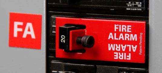
Where required by Article 760, the fire alarm power supply must be connected to an appropriate dedicated branch circuit. The overcurrent protective device and disconnecting means must be properly identified and protected against unauthorized operation in accordance with the applicable NEC requirements.
The exact requirements can depend on whether the equipment is supplying power-limited or non-power-limited fire alarm circuits and on the adopted NEC edition.
What About GFCI and AFCI Protection?
This subject is frequently oversimplified in fire alarm discussions.
Do not use the blanket rule that a fire alarm circuit can never have GFCI or AFCI protection. NEC requirements and exceptions must be evaluated based on the application, location, wiring method and adopted code edition.
Where AFCI or GFCI requirements would otherwise apply, review the applicable NEC article and fire alarm provisions carefully before determining whether an exception applies.
Fire Alarm Equipment and Circuit Identification
Fire alarm equipment supplying power-limited circuits must be identified so installers and service technicians can determine which circuits are power limited.
Proper identification becomes particularly important where power-limited and non-power-limited conductors enter the same fire alarm equipment enclosure.
Always follow the terminal markings, equipment listing and manufacturer's installation instructions when determining permitted conductor routing and separation inside equipment.
Fire Alarm Cable Support and Installation
Fire alarm cable should be installed in a neat and workmanlike manner and supported using methods suitable for the cable and installation environment.
Exposed fire alarm cable must be protected from physical damage and properly supported by the building structure or by an approved supporting method.
Do not use another raceway as a convenient support for fire alarm cable. Fire alarm cable should not simply be strapped to the exterior of conduit, piping or another raceway as a substitute for proper cable support.
Above suspended ceilings, fire alarm wiring should be independently supported in accordance with the applicable NEC requirements rather than resting on the ceiling grid or ceiling tiles.
Protecting Fire Alarm Cable From Nails and Screws
One of the most practical NEC requirements for installers involves protecting concealed cable from physical damage caused by nails and screws.
Where fire alarm cable passes through framing members near the edge of the framing, sufficient clearance must be maintained or an approved steel plate or equivalent mechanical protection must be installed where required.
This is especially important near:
- Door frames
- Baseboards
- Drywall attachment points
- Cabinetry
- Wall-mounted equipment
- Other locations where screws or nails can penetrate the framing

Fire Alarm Cable Through Walls and Floors
Where fire alarm conductors pass through walls, floors or other areas where they can be exposed to physical damage, additional mechanical protection can be required.
The required protection depends on the wiring method, location and construction of the building.
Remember that mechanical protection and firestopping are two different issues.
A cable penetration through a rated wall or floor must maintain the required fire-resistance rating using an approved firestop system suitable for the penetration and construction assembly.


Fire Alarm Cable Separation From 120V and Power Wiring
Fire alarm cable separation is one of the most misunderstood portions of NEC Article 760.
Under the 2023 NEC Article 760 framework, power-limited fire alarm conductors generally cannot occupy the same cable, cable tray, compartment, enclosure, raceway, outlet box or similar fitting with electric light, power, Class 1, non-power-limited fire alarm and certain other higher-energy circuit conductors unless one of the permitted conditions applies.
Permitted arrangements can include installations using:
- Listed or permitted barriers.
- Separate raceways within an enclosure.
- Associated-system provisions inside equipment.
- Required conductor separation.
- Other specific conditions permitted by the applicable NEC section.
PLFA Conductors Inside Fire Alarm Equipment
Power conductors and power-limited fire alarm conductors can sometimes enter the same equipment enclosure because both are required for connection to that equipment.
Where the NEC associated-system provisions are used, conductor routing and separation must comply with the applicable requirements. A commonly encountered requirement is maintaining separation between power-limited fire alarm conductors and higher-energy conductors within the enclosure unless another permitted protection method is used.
Always follow the fire alarm equipment manufacturer's internal wiring and separation instructions in addition to the NEC.
Class 1, Class 2 and Class 3 Circuits
Fire alarm technicians frequently encounter other limited-energy circuits in the same building, including security, access control, communications, HVAC controls and other signaling systems.
The fact that two circuits are both "low voltage" does not automatically mean they can share a raceway, enclosure or cable tray.
Class 1 Circuits
Class 1 circuits have different power and wiring characteristics from PLFA circuits. Where PLFA conductors are installed near Class 1 circuits, the applicable separation requirements must be followed.
Class 2 and Class 3 Circuits
Class 2 and Class 3 circuits are limited-energy circuits commonly encountered in control, signaling, communications and similar systems.
Whether PLFA conductors can share an enclosure, raceway, cable tray or routing assembly with these circuits depends on the circuit classification, conductor insulation, function and the specific NEC permission being used.
Do not use "it's all low voltage" as the installation rule.
Can Fire Alarm Wire Share Conduit With Other Low-Voltage Wiring?
Sometimes, but not automatically.
The answer depends on the classification of every circuit involved and the NEC rules applicable to those circuits.
Before combining fire alarm wiring with another system, determine:
- Whether the fire alarm circuit is PLFA or NPLFA.
- The classification of the other circuit.
- Whether the circuits are functionally associated.
- The insulation ratings of the conductors.
- Whether the NEC specifically permits the circuits to occupy the same raceway or enclosure.
- Whether the equipment listing or manufacturer prohibits the arrangement.
FPL, FPLR and FPLP Fire Alarm Cable
Power-limited fire alarm cable is marked according to its listing and permitted application.
FPL Cable
FPL is general-purpose power-limited fire alarm cable. Its use is limited to locations where a higher-rated riser or plenum cable is not required.
FPLR Cable
FPLR is riser-rated power-limited fire alarm cable intended for qualifying vertical applications and other locations where its listing permits its use.
FPLP Cable
FPLP is plenum-rated power-limited fire alarm cable and is suitable for applications requiring a plenum-rated fire alarm cable.
Fire Alarm Cable Substitutions
The NEC permits certain higher-rated cables to substitute for lower-rated power-limited fire alarm cables.
A useful hierarchy to remember is:
- FPLP: CMP can be a permitted substitute.
- FPLR: permitted substitutions can include CMP, FPLP and CMR.
- FPL: permitted substitutions can include CMP, FPLP, CMR, FPLR, CMG and CM.
Important: Cable substitution requirements are an area being reorganized in newer NEC editions. Verify the applicable section in the NEC edition adopted for your project rather than relying solely on an older Article 760 section number.
Fire Alarm Conductor Size
Conductor size must comply with the applicable NEC requirements as well as the listing and installation instructions of the connected fire alarm equipment.
Smaller conductors can be permitted under specific listed conditions, while single conductors are subject to their applicable minimum-size requirements.
Remember that NEC minimum conductor size does not determine whether the wire is large enough for the actual fire alarm circuit.
Notification appliance circuits and other powered circuits must also be evaluated for voltage drop, current draw, circuit length and the fire alarm manufacturer's requirements.
For a complete calculation example, see our Fire Alarm Voltage Drop Calculator & NAC Calculation Guide.
Fire Alarm Conduit Fill
When fire alarm conductors are installed in raceway, conduit fill must comply with the applicable NEC Chapter 9 requirements.
Conduit fill depends on factors including:
- Raceway type.
- Raceway trade size.
- Number of conductors or cables.
- Conductor insulation type.
- Conductor or cable dimensions.
The NEC Chapter 9 tables and applicable annex tables can be used to determine the permitted number of conductors for common raceway and conductor combinations.
Example: EMT Conduit Fill
The original example below uses EMT and 14 AWG THHN conductors. When using a conduit-fill table, make sure you select the correct raceway type, trade size and conductor insulation before reading the permitted quantity.

NEC Article 760 Field Checklist
- Identify whether each fire alarm circuit is PLFA or NPLFA.
- Verify the fire alarm power-source listing.
- Verify the dedicated branch-circuit requirements.
- Properly identify the fire alarm circuit and disconnecting means.
- Follow manufacturer requirements for conductor routing inside equipment.
- Use the correct FPL, FPLR or FPLP cable for the installation environment.
- Support exposed fire alarm cable properly.
- Do not support fire alarm cable from unrelated raceways or piping.
- Protect wiring from nails, screws and other physical damage.
- Properly firestop penetrations through rated assemblies.
- Verify separation from electric light, power and Class 1 circuits.
- Verify compatibility before combining PLFA with Class 2 or Class 3 circuits.
- Verify conductor size against equipment listings and circuit requirements.
- Calculate voltage drop where applicable.
- Verify conduit fill for raceway installations.
- Check the NEC edition adopted by the AHJ.
Frequently Asked Questions About Fire Alarm Wiring
What NEC article covers fire alarm wiring?
NEC Article 760 covers fire alarm system circuits. Other NEC articles can also apply depending on the power source, wiring method, circuit classification, building conditions and equipment involved.
What is the difference between PLFA and NPLFA?
PLFA means power-limited fire alarm circuit. NPLFA means non-power-limited fire alarm circuit. The classification affects the permitted wiring methods, conductor requirements and separation rules.
Can fire alarm wire be installed with 120V wiring?
Power-limited fire alarm wiring generally must be separated from electric light and power conductors unless a specific NEC permission applies, such as an approved barrier, raceway arrangement or associated-equipment condition.
Does fire alarm wire always have to be 2 inches away from power?
No. The commonly repeated "2-inch rule" does not describe every permitted NEC installation. Separation requirements depend on the circuit types, wiring methods, raceways, enclosures and specific NEC provisions involved.
Can fire alarm cable be strapped to conduit?
Fire alarm cable should not use unrelated raceway or piping as a substitute for its required structural support. Use approved cable-support methods appropriate for the installation.
What is the difference between FPL, FPLR and FPLP?
FPL is general-purpose power-limited fire alarm cable, FPLR is riser-rated fire alarm cable and FPLP is plenum-rated fire alarm cable. The required rating depends on where the cable is installed.
Can fire alarm wiring share conduit with other low-voltage wiring?
It can be permitted in certain situations, but "low voltage" alone is not enough to make the installation compliant. The classification, insulation, function and NEC requirements for each circuit must be evaluated.
Does the NEC determine fire alarm wire size?
The NEC establishes applicable conductor requirements, but circuit design must also consider equipment listings, manufacturer instructions, current draw, circuit length and voltage drop.
Related Fire Alarm Wiring Guides
Fire Alarm Voltage Drop Calculator & NAC Calculation Guide
How to Use a Multimeter for Fire Alarm Systems
Fire Alarm Ground Fault Troubleshooting
520 Hz Fire Alarm Requirements
Code Disclaimer: NEC requirements vary by adopted edition and jurisdiction. Always verify the locally adopted edition of NFPA 70, applicable amendments, fire alarm equipment listings, manufacturer instructions and AHJ requirements before final design or installation.
