Showing posts with label Fire Alarm Installation. Show all posts

Monday, September 16, 2019

NEC Article 760 Fire Alarm Wiring Requirements | Complete Guide

NEC Article 760 contains the National Electrical Code requirements for fire alarm wiring and circuits. For fire alarm technicians, designers and installers, Article 760 is one of the most important electrical code articles to understand because it addresses power sources, wiring methods, conductor protection, cable separation, cable types and other installation requirements for fire alarm circuits.

This guide explains the practical requirements for power-limited fire alarm (PLFA) and non-power-limited fire alarm (NPLFA) circuits, including fire alarm cable separation, support, mechanical protection, FPL/FPLR/FPLP cable, branch-circuit requirements and conduit fill.

Code Edition Note: NEC section numbers and requirements can change between editions. This article primarily follows the 2023 NEC Article 760 structure. Always verify the NEC edition adopted by your jurisdiction and any local amendments before designing or installing a fire alarm system.

What Is NEC Article 760?

Article 760 of NFPA 70, the National Electrical Code, addresses fire alarm system wiring and circuits.

Fire alarm circuits generally fall into two categories:

  • Power-Limited Fire Alarm (PLFA) circuits
  • Non-Power-Limited Fire Alarm (NPLFA) circuits

Understanding which type of circuit you are working with is critical because the permitted wiring methods, conductor requirements and separation rules can be different.

Power-Limited vs. Non-Power-Limited Fire Alarm Circuits

Power-Limited Fire Alarm Circuits (PLFA)

A power-limited fire alarm circuit receives its power from a source specifically listed and identified for power-limited fire alarm use.

This is the category technicians encounter on many modern fire alarm systems. Examples can include signaling line circuits, initiating device circuits, notification appliance circuits and other circuits when the equipment manufacturer identifies those outputs as power limited.

Never determine that a circuit is power limited simply because it operates at low voltage. The power source and equipment listing determine whether the circuit qualifies as a PLFA circuit.

Non-Power-Limited Fire Alarm Circuits (NPLFA)

A non-power-limited fire alarm circuit is a fire alarm circuit that does not meet the requirements for classification as power limited.

NPLFA circuits are subject to different wiring requirements and should not automatically be treated like the low-voltage PLFA wiring commonly encountered in modern fire alarm installations.

Field Tip: When you are unsure whether a fire alarm circuit is power limited, check the fire alarm control panel, power supply or module markings and the manufacturer's installation instructions. Do not make the determination from voltage alone.

Power Sources for Power-Limited Fire Alarm Circuits

PLFA circuits must be supplied from a power source permitted for power-limited fire alarm use. Common examples include listed fire alarm control units, listed power supplies and equipment specifically identified for supplying PLFA circuits.

The equipment markings and manufacturer's documentation are critical because they identify which outputs are power limited.

NEC power-limited fire alarm power source limitation tables
NEC power-source limitation information for power-limited circuits.

Fire Alarm Branch Circuit Requirements

The branch circuit supplying fire alarm equipment is an important part of the system and should not be treated like an ordinary convenience circuit.

Where required by Article 760, the fire alarm power supply must be connected to an appropriate dedicated branch circuit. The overcurrent protective device and disconnecting means must be properly identified and protected against unauthorized operation in accordance with the applicable NEC requirements.

The exact requirements can depend on whether the equipment is supplying power-limited or non-power-limited fire alarm circuits and on the adopted NEC edition.
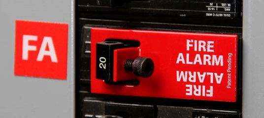
Fire alarm dedicated branch circuit breaker lock
Example of a locking device used to prevent unauthorized operation of a fire alarm branch-circuit breaker.

What About GFCI and AFCI Protection?

This subject is frequently oversimplified in fire alarm discussions.

Do not use the blanket rule that a fire alarm circuit can never have GFCI or AFCI protection. NEC requirements and exceptions must be evaluated based on the application, location, wiring method and adopted code edition.

Where AFCI or GFCI requirements would otherwise apply, review the applicable NEC article and fire alarm provisions carefully before determining whether an exception applies.

Fire Alarm Equipment and Circuit Identification

Fire alarm equipment supplying power-limited circuits must be identified so installers and service technicians can determine which circuits are power limited.

Proper identification becomes particularly important where power-limited and non-power-limited conductors enter the same fire alarm equipment enclosure.

Always follow the terminal markings, equipment listing and manufacturer's installation instructions when determining permitted conductor routing and separation inside equipment.

Fire Alarm Cable Support and Installation

Fire alarm cable should be installed in a neat and workmanlike manner and supported using methods suitable for the cable and installation environment.

Exposed fire alarm cable must be protected from physical damage and properly supported by the building structure or by an approved supporting method.

Do not use another raceway as a convenient support for fire alarm cable. Fire alarm cable should not simply be strapped to the exterior of conduit, piping or another raceway as a substitute for proper cable support.

Above suspended ceilings, fire alarm wiring should be independently supported in accordance with the applicable NEC requirements rather than resting on the ceiling grid or ceiling tiles.

Protecting Fire Alarm Cable From Nails and Screws

One of the most practical NEC requirements for installers involves protecting concealed cable from physical damage caused by nails and screws.

Where fire alarm cable passes through framing members near the edge of the framing, sufficient clearance must be maintained or an approved steel plate or equivalent mechanical protection must be installed where required.

This is especially important near:

  • Door frames
  • Baseboards
  • Drywall attachment points
  • Cabinetry
  • Wall-mounted equipment
  • Other locations where screws or nails can penetrate the framing
Steel protection plate protecting fire alarm cable in wall framing
Steel protection plate used to help protect concealed wiring from nails and screws.

Fire Alarm Cable Through Walls and Floors

Where fire alarm conductors pass through walls, floors or other areas where they can be exposed to physical damage, additional mechanical protection can be required.

The required protection depends on the wiring method, location and construction of the building.

Remember that mechanical protection and firestopping are two different issues.

A cable penetration through a rated wall or floor must maintain the required fire-resistance rating using an approved firestop system suitable for the penetration and construction assembly.

Fire alarm raceway penetration protected with listed firestop material
Example of a penetration protected with firestop material.
Listed firestop grommet for fire alarm cable penetration
Example of a listed firestop product designed for cable penetrations.

Fire Alarm Cable Separation From 120V and Power Wiring

Fire alarm cable separation is one of the most misunderstood portions of NEC Article 760.

Under the 2023 NEC Article 760 framework, power-limited fire alarm conductors generally cannot occupy the same cable, cable tray, compartment, enclosure, raceway, outlet box or similar fitting with electric light, power, Class 1, non-power-limited fire alarm and certain other higher-energy circuit conductors unless one of the permitted conditions applies.

Permitted arrangements can include installations using:

  • Listed or permitted barriers.
  • Separate raceways within an enclosure.
  • Associated-system provisions inside equipment.
  • Required conductor separation.
  • Other specific conditions permitted by the applicable NEC section.
Important: The familiar statement that fire alarm cable must always remain "2 inches from 120V" is an oversimplification. The NEC contains different rules depending on whether conductors are in raceways, enclosures, associated equipment or other permitted wiring arrangements.

PLFA Conductors Inside Fire Alarm Equipment

Power conductors and power-limited fire alarm conductors can sometimes enter the same equipment enclosure because both are required for connection to that equipment.

Where the NEC associated-system provisions are used, conductor routing and separation must comply with the applicable requirements. A commonly encountered requirement is maintaining separation between power-limited fire alarm conductors and higher-energy conductors within the enclosure unless another permitted protection method is used.

Always follow the fire alarm equipment manufacturer's internal wiring and separation instructions in addition to the NEC.

Class 1, Class 2 and Class 3 Circuits

Fire alarm technicians frequently encounter other limited-energy circuits in the same building, including security, access control, communications, HVAC controls and other signaling systems.

The fact that two circuits are both "low voltage" does not automatically mean they can share a raceway, enclosure or cable tray.

Class 1 Circuits

Class 1 circuits have different power and wiring characteristics from PLFA circuits. Where PLFA conductors are installed near Class 1 circuits, the applicable separation requirements must be followed.

Class 2 and Class 3 Circuits

Class 2 and Class 3 circuits are limited-energy circuits commonly encountered in control, signaling, communications and similar systems.

Whether PLFA conductors can share an enclosure, raceway, cable tray or routing assembly with these circuits depends on the circuit classification, conductor insulation, function and the specific NEC permission being used.

Do not use "it's all low voltage" as the installation rule.

Can Fire Alarm Wire Share Conduit With Other Low-Voltage Wiring?

Sometimes, but not automatically.

The answer depends on the classification of every circuit involved and the NEC rules applicable to those circuits.

Before combining fire alarm wiring with another system, determine:

  • Whether the fire alarm circuit is PLFA or NPLFA.
  • The classification of the other circuit.
  • Whether the circuits are functionally associated.
  • The insulation ratings of the conductors.
  • Whether the NEC specifically permits the circuits to occupy the same raceway or enclosure.
  • Whether the equipment listing or manufacturer prohibits the arrangement.

FPL, FPLR and FPLP Fire Alarm Cable

Power-limited fire alarm cable is marked according to its listing and permitted application.

FPL Cable

FPL is general-purpose power-limited fire alarm cable. Its use is limited to locations where a higher-rated riser or plenum cable is not required.

FPLR Cable

FPLR is riser-rated power-limited fire alarm cable intended for qualifying vertical applications and other locations where its listing permits its use.

FPLP Cable

FPLP is plenum-rated power-limited fire alarm cable and is suitable for applications requiring a plenum-rated fire alarm cable.

Fire Alarm Cable Substitutions

The NEC permits certain higher-rated cables to substitute for lower-rated power-limited fire alarm cables.

A useful hierarchy to remember is:

  • FPLP: CMP can be a permitted substitute.
  • FPLR: permitted substitutions can include CMP, FPLP and CMR.
  • FPL: permitted substitutions can include CMP, FPLP, CMR, FPLR, CMG and CM.

Important: Cable substitution requirements are an area being reorganized in newer NEC editions. Verify the applicable section in the NEC edition adopted for your project rather than relying solely on an older Article 760 section number.

Fire Alarm Conductor Size

Conductor size must comply with the applicable NEC requirements as well as the listing and installation instructions of the connected fire alarm equipment.

Smaller conductors can be permitted under specific listed conditions, while single conductors are subject to their applicable minimum-size requirements.

Remember that NEC minimum conductor size does not determine whether the wire is large enough for the actual fire alarm circuit.

Notification appliance circuits and other powered circuits must also be evaluated for voltage drop, current draw, circuit length and the fire alarm manufacturer's requirements.

For a complete calculation example, see our Fire Alarm Voltage Drop Calculator & NAC Calculation Guide.

Fire Alarm Conduit Fill

When fire alarm conductors are installed in raceway, conduit fill must comply with the applicable NEC Chapter 9 requirements.

Conduit fill depends on factors including:

  • Raceway type.
  • Raceway trade size.
  • Number of conductors or cables.
  • Conductor insulation type.
  • Conductor or cable dimensions.

The NEC Chapter 9 tables and applicable annex tables can be used to determine the permitted number of conductors for common raceway and conductor combinations.

Example: EMT Conduit Fill

The original example below uses EMT and 14 AWG THHN conductors. When using a conduit-fill table, make sure you select the correct raceway type, trade size and conductor insulation before reading the permitted quantity.

NEC EMT conduit fill table for fire alarm wiring
Example NEC conduit-fill table for EMT and individual conductors.

NEC Article 760 Field Checklist

  • Identify whether each fire alarm circuit is PLFA or NPLFA.
  • Verify the fire alarm power-source listing.
  • Verify the dedicated branch-circuit requirements.
  • Properly identify the fire alarm circuit and disconnecting means.
  • Follow manufacturer requirements for conductor routing inside equipment.
  • Use the correct FPL, FPLR or FPLP cable for the installation environment.
  • Support exposed fire alarm cable properly.
  • Do not support fire alarm cable from unrelated raceways or piping.
  • Protect wiring from nails, screws and other physical damage.
  • Properly firestop penetrations through rated assemblies.
  • Verify separation from electric light, power and Class 1 circuits.
  • Verify compatibility before combining PLFA with Class 2 or Class 3 circuits.
  • Verify conductor size against equipment listings and circuit requirements.
  • Calculate voltage drop where applicable.
  • Verify conduit fill for raceway installations.
  • Check the NEC edition adopted by the AHJ.

Frequently Asked Questions About Fire Alarm Wiring

What NEC article covers fire alarm wiring?

NEC Article 760 covers fire alarm system circuits. Other NEC articles can also apply depending on the power source, wiring method, circuit classification, building conditions and equipment involved.

What is the difference between PLFA and NPLFA?

PLFA means power-limited fire alarm circuit. NPLFA means non-power-limited fire alarm circuit. The classification affects the permitted wiring methods, conductor requirements and separation rules.

Can fire alarm wire be installed with 120V wiring?

Power-limited fire alarm wiring generally must be separated from electric light and power conductors unless a specific NEC permission applies, such as an approved barrier, raceway arrangement or associated-equipment condition.

Does fire alarm wire always have to be 2 inches away from power?

No. The commonly repeated "2-inch rule" does not describe every permitted NEC installation. Separation requirements depend on the circuit types, wiring methods, raceways, enclosures and specific NEC provisions involved.

Can fire alarm cable be strapped to conduit?

Fire alarm cable should not use unrelated raceway or piping as a substitute for its required structural support. Use approved cable-support methods appropriate for the installation.

What is the difference between FPL, FPLR and FPLP?

FPL is general-purpose power-limited fire alarm cable, FPLR is riser-rated fire alarm cable and FPLP is plenum-rated fire alarm cable. The required rating depends on where the cable is installed.

Can fire alarm wiring share conduit with other low-voltage wiring?

It can be permitted in certain situations, but "low voltage" alone is not enough to make the installation compliant. The classification, insulation, function and NEC requirements for each circuit must be evaluated.

Does the NEC determine fire alarm wire size?

The NEC establishes applicable conductor requirements, but circuit design must also consider equipment listings, manufacturer instructions, current draw, circuit length and voltage drop.


Related Fire Alarm Wiring Guides

Fire Alarm Voltage Drop Calculator & NAC Calculation Guide
How to Use a Multimeter for Fire Alarm Systems
Fire Alarm Ground Fault Troubleshooting
520 Hz Fire Alarm Requirements

Code Disclaimer: NEC requirements vary by adopted edition and jurisdiction. Always verify the locally adopted edition of NFPA 70, applicable amendments, fire alarm equipment listings, manufacturer instructions and AHJ requirements before final design or installation.

Tuesday, December 19, 2017

OSID Beam Smoke Detectors | Installation, Alignment & Real-World Review

OSID BEAM SMOKE DETECTION: QUICK ANSWER

Xtralis OSID, or Open-area Smoke Imaging Detection, is an imaging-based projected-beam smoke detection system designed for large open spaces such as stadiums, warehouses, atriums, arenas, gymnasiums and other difficult smoke-detection environments.

Instead of relying on a conventional beam detector and reflector arrangement, OSID uses an imager and one or more emitters. The system analyzes dual-wavelength ultraviolet (UV) and infrared (IR) light to distinguish smoke from many environmental and obstruction conditions.

I originally wrote this article after installing OSID in one of the more challenging real-world environments I could have asked for: the Oakland Coliseum sports complex.

Why I Originally Wrote About OSID

When I first started working with Xtralis OSID, we had about as difficult a real-world environment as you could ask for to evaluate beam-type smoke detection: the Oakland Coliseum.

At the time, the Oakland Coliseum was home to the Oakland Raiders, while the Golden State Warriors played next door at the arena within the Coliseum sports complex.

This was not a quiet warehouse where a beam detector could spend its life looking across an empty ceiling.

It was a major sports and entertainment environment with thousands of fans, vibration and structural movement, changing atmospheric conditions, smoke and haze, airflow, and all the activity associated with packed sporting events.

People jumping and cheering might sound completely unrelated to fire alarm detection until you remember that traditional projected-beam detectors can be affected by movement and alignment. When detection equipment is installed high above a floor, every unnecessary alignment or service trip can become a major event.

That is where OSID got my attention.

In my field experience, the OSID system performed extremely well in this demanding environment. The imaging technology and its tolerance for movement and environmental conditions made a strong impression on me, especially after years of dealing with conventional beam-detector alignment.

REAL FIELD EXPERIENCE

The photographs throughout this article are not manufacturer promotional photographs or stock images.

They are photographs from our actual OSID installation work.

That real-world experience is one of the main reasons I originally wrote this article and why I wanted to preserve these photographs in this updated technical guide.

Interestingly, the characteristics that impressed me in the field remain central to how Xtralis describes OSID today, including tolerance to building movement, vibration and challenging environmental conditions.

What Is a Beam Smoke Detector?

A projected-beam smoke detector is a fire alarm detection device that monitors smoke across a large open space using a projected optical path.

Instead of installing numerous spot-type smoke detectors throughout a large ceiling area, a properly designed beam detection system can monitor a much larger area along its beam path.

Beam smoke detection is commonly considered for applications such as:

  • Warehouses
  • Atriums
  • Gymnasiums
  • Arenas and stadiums
  • Aircraft hangars
  • Large manufacturing areas
  • Transportation facilities
  • Entertainment venues
  • Other large or high-ceiling spaces

The actual detector spacing, beam location, mounting height and application must be designed in accordance with the adopted fire alarm code, the detector's listing and the manufacturer's published instructions.

Why Can Traditional Beam Detectors Be Difficult?

Whether you have been in the fire alarm industry for a month or several decades, there is a good chance you have heard technicians express a love-hate relationship with beam detectors.

The concept is excellent. Protect a large open area without installing dozens of individual detectors, miles of additional wire and conduit, and numerous devices in locations that may be extremely difficult to access.

The challenge has traditionally been installation, alignment and maintaining that alignment.

Early beam systems I worked with used separate transmitter and receiver assemblies. Later reflected-beam designs eliminated the separate receiver by sending the beam toward a reflector and measuring the light returned to the detector.

Those developments simplified wiring, but precise alignment could still require patience.

Then there is the building itself.

Large structures move. Steel expands and contracts. Roof systems react to temperature. Equipment vibrates. Crowds and building activity can introduce movement. Even a relatively small change at the mounting point can matter over a long optical path.

And unfortunately, beam detectors are rarely mounted six feet above the floor where you can casually adjust one from a stepladder.

That was the problem that made OSID so interesting to me.

What Is Xtralis OSID?

OSID stands for Open-area Smoke Imaging Detection.

Xtralis is well known in the fire alarm industry for VESDA aspirating smoke detection, but OSID takes a different approach to protecting large open areas.

The system uses two primary components:

  • Imager - the receiving and processing portion of the system.
  • Emitter - the optical source monitored by the imager.

In simplified terms, think of the imager as watching for and analyzing the light coming from one or more emitters within its field of view.

That is different from a traditional reflected-beam arrangement where precise alignment is required to send an optical beam toward a reflector and return it to the detector.

How Does OSID Detect Smoke?

One of the most important parts of OSID technology is its use of two wavelengths of light: ultraviolet (UV) and infrared (IR).

Smoke affects those wavelengths differently.

By analyzing the relative attenuation of the UV and IR signals, OSID can determine whether the optical path is behaving in a manner consistent with smoke rather than simply treating every reduction in received light as a fire condition.

This imaging and dual-wavelength approach is a major reason the technology can tolerate many conditions that can challenge conventional optical beam systems.

IMPORTANT:

Environmental tolerance does not mean that OSID can be installed anywhere without engineering consideration.

Detector selection, sensitivity, distance, field of view, beam location, mounting surfaces, airflow, ceiling geometry and environmental conditions must still comply with the current manufacturer's listing and installation instructions and the adopted fire alarm code.

OSID at the Oakland Coliseum: Why the Application Mattered

The Coliseum installation is important to this story because it demonstrates why imaging-based beam detection caught my attention in the first place.

Think about the environment inside and around a major sports venue:

  • Large open spaces
  • Long detection distances
  • Difficult device access
  • Structural movement and vibration
  • Large crowds
  • Thousands of people jumping and moving during events
  • Air movement
  • Smoke, haze and changing atmospheric conditions
  • Equipment mounted where repeated service access is expensive and inconvenient

Those are exactly the kinds of conditions that make reliable detection and stable alignment important.

In our installation, OSID proved to be remarkably stable. That experience was not a laboratory test and should not be interpreted as a universal performance guarantee. It was my real-world field experience with the technology in a demanding venue.

Years later, that installation remains one of the reasons I remember OSID so clearly.

What Makes Up an OSID Beam Detection System?

The original OSID system documented in these photographs used the OSI-10 and OSI-90 imager family along with compatible OSE emitters.

Those product families remain supported by Xtralis, but specifications and listings have evolved since this article was first written. Always use the current product documentation for a new design.

OSID Imager

Original FireAlarmsOnline field photograph showing an OSID imager with the enclosure open during installation.

Two of the best-known imagers in the OSID-DE family are the OSI-10 and OSI-90.

OSI-10

The OSI-10 uses a narrow-angle lens and monitors a single emitter.

Current Xtralis documentation identifies a 10-degree lens with an approximately 7-degree usable horizontal field of view. This distinction is worth noting because older literature, including the original version of this article, described the field of view differently.

For U.S. UL installations, the allowable detection range depends on the listed sensitivity and emitter configuration. Do not use an old blanket distance from a legacy article when designing a current installation.

OSI-90

The OSI-90 provides a much wider field of view and can monitor up to seven emitters.

Current manufacturer literature identifies approximately 80 degrees of usable horizontal field of view.

This allows one imager to monitor multiple emitters located at different positions within a large space, making the OSI-90 particularly interesting for applications such as atriums and other geometrically complex open areas.

OSID Emitters

OSID emitters have been offered in standard-power and high-power configurations, with wired and battery-powered options depending on the product and listing.

The emitter configuration matters because it can affect allowable detection distance, installation requirements and compatibility with the selected imager.

Original field photograph of an OSID emitter used with the imaging beam smoke detection system.
CURRENT-DESIGN NOTE

Xtralis publishes specific UL configuration tables for OSID-DE.

Those tables establish the allowable detection ranges for the selected imager, emitter type and sensitivity. Because those specifications can change with listings and product revisions, use the current Xtralis UL product guide and installation sheet rather than treating the numbers in an older field article as design criteria.

Single-Emitter vs. Multi-Emitter OSID Applications

One of the features that separates the OSI-90 from a traditional one-to-one beam arrangement is the ability to monitor multiple emitters from a single imager.

Multi-emitter OSID arrangement illustrating how a wide-field imager can monitor multiple emitter locations within a large space.

For a straightforward one-to-one application, a narrow-field imager and single emitter may be appropriate.

For a large atrium or another space where several optical paths are required, an OSI-90 can monitor multiple compatible emitters within its field of view.

This does not mean that simply adding emitters automatically provides a particular square-foot coverage.

The original version of this article included generalized square-foot figures. I have intentionally removed those from this updated version because projected-beam smoke detection must be designed around actual beam spacing, ceiling geometry, mounting location, airflow, listed equipment limitations and the adopted code.

OSID Installation and Mounting

One of the things I liked when first installing OSID was the mechanical design.

The imager and emitter assemblies use mounting hardware designed to make positioning and alignment practical even when the units are installed on different surfaces or at different angles.

Inside the OSID Imager

Original installation photograph showing the OSID imager electronics and field-wiring area.

The imager provides the electrical connections and configuration required for alarm, fault, power and related system functions.

Configuration details, terminal functions and switch settings can vary by hardware and firmware revision. For that reason, the current Xtralis installation sheet should be followed rather than using an old switch-setting description from this article as a commissioning instruction.

OSID Mounting Bracket

Original field photograph showing the mounting bracket used to secure and position the OSID equipment.

The mounting surface is important.

Even though OSID is designed to tolerate movement better than many conventional beam arrangements, the equipment still needs to be installed on a suitable, structurally sound surface in accordance with the manufacturer's instructions.

How to Align an OSID Beam Smoke Detector

This was one of the features that impressed me most during the original installation.

Traditional beam alignment can sometimes feel like trying to thread a needle from the opposite end of a warehouse.

OSID uses an adjustable optical assembly and alignment tools to simplify the process.

The original installation shown here used the OSP-002 laser alignment tool.

Original FireAlarmsOnline field photograph of the OSP-002 laser alignment tool used during OSID setup.

Align the Emitters First

On the system documented in this original installation, we began with the emitter side.

The adjustable ball-and-socket arrangement allowed the emitter optics to be aimed toward the imager. The laser alignment tool provided a visible reference for getting the optical assembly into the required alignment zone.

Actual field installation showing the laser alignment tool installed on the OSID emitter.

Then Align and Train the Imager

After the applicable emitters are positioned, the imager is aimed so that the required emitters fall within its usable field of view.

The imager then goes through its commissioning or training process so the system can identify the configured emitters and establish its operating reference.

The exact commissioning sequence, LED indications, timing and software procedures should be taken from the current Xtralis installation and commissioning documentation because those details can change with firmware and product revisions.

WHY TECHNICIANS CARE

Alignment is not merely an installation issue.

If a detector is mounted 30, 40 or 60 feet above the floor, every unnecessary return trip can require lifts, building access, shutdown coordination and significant labor.

A detection system that remains stable after commissioning can therefore provide a very practical service advantage.

OSID and Building Movement

This deserves its own section because it was one of the biggest reasons I became interested in OSID.

Large buildings are not perfectly rigid.

Temperature changes, structural loading, wind, vibration and normal building activity can produce movement.

With a tightly aligned traditional optical arrangement, movement at one end of a long beam path can affect alignment.

OSID's imaging approach provides a field of view in which the imager identifies the emitter rather than depending solely on an optical beam returning to one extremely precise point.

That does not make mounting requirements irrelevant, but it provides a fundamentally different approach to dealing with alignment and movement.

That difference became very real to me in the Coliseum environment.

What About Fog, Haze, Dust and Other Environmental Conditions?

This is another area where the dual-wavelength design matters.

OSID evaluates both UV and IR attenuation rather than making a decision based only on a single optical measurement.

Current manufacturer literature describes the system as designed for high immunity to many nuisance conditions and environmental interference.

That is particularly attractive in large venues, industrial environments and other applications where dust, haze, steam, reflections, temporary obstructions or environmental changes may be present.

Again, this is not permission to ignore the environment during design. The expected conditions still need to fall within the equipment's listed operating parameters.

Where Does OSID Make Sense?

OSID deserves consideration where projected-beam smoke detection is appropriate and the application benefits from imaging-based detection.

Examples can include:

  • Large warehouses
  • Stadiums and arenas
  • Atriums
  • Gymnasiums
  • Entertainment venues
  • Large manufacturing spaces
  • Transportation facilities
  • High-ceiling open areas
  • Applications where conventional beam alignment or movement is a concern
  • Retrofits where the system configuration supports an OSID solution

When Might OSID Not Be the Best Detection Method?

No smoke-detection technology is automatically the best solution for every building.

Depending on the hazard, ceiling configuration, airflow, required response, access and project objectives, the designer might instead consider:

  • Spot-type smoke detection
  • Conventional projected-beam smoke detection
  • Aspirating smoke detection such as VESDA
  • Air-sampling detection
  • Other listed detection technologies appropriate to the hazard

The correct question is not simply, "Which detector is coolest?"

The real question is:

WHAT DETECTION METHOD BEST FITS THE HAZARD, BUILDING AND REQUIRED RESPONSE?

NFPA 72 Requirements for Projected-Beam Smoke Detection

OSID is still fire alarm smoke detection equipment and must be designed and installed within the applicable code and listing framework.

NFPA 72 addresses projected-beam smoke detectors as part of the smoke-detection requirements in Chapter 17.

A key principle is that projected-beam smoke detector spacing and placement must follow the manufacturer's published instructions.

NFPA guidance also treats each projected beam as comparable to a row of spot-type smoke detectors for spacing purposes.

The designer must also consider factors such as:

  • Ceiling geometry
  • Ceiling height
  • Beam spacing
  • Distance from sidewalls
  • Airflow
  • Smoke stratification
  • Structural obstructions
  • Accessibility for inspection, testing and maintenance
  • The detector manufacturer's listing and installation instructions
CODE NOTE:

Do not use a generic square-foot coverage number to lay out projected-beam smoke detectors.

Beam placement is a design exercise involving the adopted NFPA 72 edition, ceiling configuration, environmental conditions and the specific detector manufacturer's listed installation requirements.

Inspection, Testing and Maintenance

High-ceiling detection still has to be inspected, tested and maintained.

That consideration should begin during design, not after someone discovers that a detector can only be reached with a specialized lift.

OSID provides alarm and fault supervision along with diagnostic capabilities that can assist technicians with commissioning and troubleshooting.

Xtralis continues to provide OSID commissioning documentation and diagnostic software for the OSI-10/OSI-90 family.

Always use the current maintenance and test procedure applicable to the installed model, firmware and listing.

What I Think About OSID After Real-World Installation Experience

When I originally wrote this article in 2017, OSID was still relatively new technology to many technicians I worked with.

My enthusiasm came from actually installing it and watching it perform in an environment where I expected beam detection to be challenging.

The Oakland Coliseum sports complex gave us vibration, movement, crowds, difficult access and changing environmental conditions.

The system impressed me.

That does not mean OSID is automatically the correct detector for every large space.

It means that when imaging-based projected-beam detection fits the design criteria, OSID offers a very interesting alternative to traditional beam arrangements, particularly where alignment stability and environmental tolerance matter.

And years after I originally wrote about it, the OSI-10/OSI-90 product family remains supported by Xtralis.

OSID Beam Detector Frequently Asked Questions

What does OSID stand for?

OSID stands for Open-area Smoke Imaging Detection. It is an imaging-based projected-beam smoke detection technology developed by Xtralis.

How does an OSID beam detector work?

An OSID imager monitors light produced by one or more emitters and analyzes ultraviolet and infrared wavelengths. Changes in those optical signals allow the system to detect conditions consistent with smoke while providing resistance to many nuisance conditions.

What is the difference between OSI-10 and OSI-90?

The OSI-10 is a narrow-field imager intended for a single emitter. The OSI-90 provides a much wider field of view and can monitor multiple compatible emitters. Exact ranges and configurations depend on the current listing, sensitivity and emitter selection.

How many emitters can an OSI-90 monitor?

The OSI-90 can monitor up to seven compatible emitters when configured in accordance with the manufacturer's requirements.

Can OSID be used in a stadium?

Stadiums and other large open venues are among the types of applications identified for OSID. The system still must be engineered for the specific building, environment, beam layout and adopted code requirements.

Does OSID tolerate building movement?

OSID's imaging approach and field of view are designed to provide greater tolerance to movement and alignment variation than a narrowly aligned conventional beam arrangement. The equipment must still be mounted according to the manufacturer's requirements.

Can fog or haze cause problems with beam smoke detectors?

Atmospheric conditions can affect optical smoke detection. OSID uses dual UV and IR wavelengths and imaging algorithms specifically intended to help distinguish smoke from many nuisance and environmental conditions. The expected environment must remain within the product's listed operating limitations.

Does OSID replace every conventional beam detector?

No. OSID is one detection option. Conventional projected-beam detection, spot detection and aspirating smoke detection can all be appropriate depending on the building and fire protection objectives.

Does NFPA 72 allow OSID beam smoke detectors?

Projected-beam smoke detection is addressed by NFPA 72. The detector must be listed for its application and installed according to the adopted code and manufacturer's published instructions.

Current Xtralis OSID Technical Information

Because product listings, firmware and installation requirements can change, use the current manufacturer's documentation when designing, installing, commissioning or servicing OSID equipment.

The official Xtralis OSID technical library contains current product guides, UL installation sheets, commissioning information, technical bulletins and diagnostic software.

View the Official Xtralis OSID Technical Documentation

The Bottom Line

WHY OSID MADE AN IMPRESSION ON ME

I had spent years dealing with the compromises of traditional beam detection when I first encountered OSID.

Then I had the opportunity to install it in a place that could really put the concept to work: the Oakland Coliseum sports complex.

Huge spaces. Difficult access. Vibration. Movement. Crowds. Changing atmospheric conditions. Thousands of people making a building feel very much alive.

And the OSID system performed extremely well in my field experience.

That is why I originally wrote this article.

The technology should still be selected and designed like any other life-safety detection system: based on the hazard, building, adopted NFPA 72 requirements, listing and manufacturer's instructions.

But when imaging-based beam detection fits the application, OSID provides an approach to open-area smoke detection that is very different from the traditional beam detectors many technicians grew up fighting with.

Technical Disclaimer: Fire alarm systems are life-safety systems. Detector selection, spacing, installation, commissioning, testing and maintenance should be performed by qualified personnel in accordance with the locally adopted codes, approved design documents, equipment listing and manufacturer's published instructions. Product specifications can change. Always verify current Xtralis documentation for the exact equipment being installed.

Saturday, April 29, 2017

Is a Smoke Detector Required Above a Fire Alarm Control Panel? | NFPA 72

NFPA 72 decision guide for determining when early-warning smoke or heat detection is required at fire alarm control equipment. Always verify the locally adopted code edition and AHJ requirements.

One of the most common questions we hear from fire alarm technicians, designers and inspectors is: "Do I need a smoke detector above the fire alarm control panel?"

The answer is not always.

Quick Answer:

NFPA 72 requires early-warning fire detection at specified fire alarm control equipment when that equipment is located in an area that is not continuously occupied, unless an applicable permitted condition applies.

Where required, an automatic smoke detector is normally used. An automatic heat detector can be used where ambient conditions prohibit the installation of a smoke detector.

Also, the detector does not necessarily have to be mounted literally above the panel. The NFPA 72 language is based on detection at the location of the equipment, with detector placement following the applicable Chapter 17 location requirements.

That distinction matters because the phrase "smoke detector above the FACP" has become common field terminology. It is convenient shorthand, but it can make the requirement sound much simpler than it actually is.

Let's break it down.

What Equipment Is NFPA 72 Trying to Protect?

NFPA 72 Section 10.4.5 addresses early-warning fire detection at certain equipment located in areas that are not continuously occupied.

The equipment addressed includes:

  • Fire alarm control units
  • Notification appliance circuit (NAC) power extenders
  • Supervising station transmitting equipment

The purpose is straightforward: a fire developing at or near critical fire alarm equipment could damage that equipment before the system performs the functions it is supposed to perform.

Early detection provides an opportunity for the fire condition to be detected and reported before critical equipment is disabled by the fire.

Important: The requirement should not automatically be applied to every piece of fire alarm equipment on the wall. NFPA explanatory material distinguishes the applicable control equipment from devices such as annunciators and addressable field devices.

Is a Smoke Detector Always Required Above the FACU?

No.

The first question should not be, "Where do I put the smoke detector?"

The first question should be:

Is early-warning detection required at this equipment location in the first place?

Several conditions can change the answer.

1. Is the Area Continuously Occupied?

Section 10.4.5 applies to equipment located in areas that are not continuously occupied.

That means a room or area being occupied occasionally throughout the business day should not automatically be treated as continuously occupied.

For example, an office where employees come and go, a lobby that becomes vacant after normal business hours, or an electrical room entered periodically by maintenance personnel is very different from a location staffed continuously.

A security command center or similar location with personnel actually present continuously may fall outside the not-continuously-occupied condition addressed by 10.4.5.

Field Tip: Do not interpret "continuously occupied" as "people are usually around." The actual occupancy and staffing arrangement matters. When the condition is questionable, coordinate the interpretation with the AHJ.

2. Does the Room Already Have Total Smoke Detection Coverage?

Another frequently misunderstood situation occurs when the room containing the FACU already has smoke detection throughout the space.

NFPA explanatory material indicates that where the room or area containing the control unit already has total smoke detection coverage, an additional smoke detector solely for the purpose of protecting the control unit is not necessary.

In other words, the requirement is not necessarily:

Existing detector + another special detector directly above the panel.

If the required detection objective is already being accomplished by the room's smoke detection system, another dedicated detector at the panel may not be necessary.

This is one reason designers should evaluate the entire detection layout instead of automatically adding a detector directly over every FACU.

3. What If the Room Is Large?

This brings up another interesting point.

The detector required specifically for protection of the control equipment is intended to provide selective coverage at the equipment location.

NFPA explanatory material has clarified that where total smoke detection is not otherwise provided, the intent is not necessarily to redesign the entire room for complete smoke detector coverage simply because a detector is required at the control unit.

The objective is protection at the equipment location.

If the building or room is required to have complete smoke detection for some other reason, those separate requirements still apply.

4. What About Dedicated-Function Fire Alarm Systems?

This is where the question becomes considerably more interesting.

A building fire alarm system generally serves the overall fire alarm needs of the building and can provide occupant notification, fire department notification, or other building-wide functions.

A dedicated-function fire alarm system is installed specifically to perform one or more particular fire-safety functions where a complete building fire alarm system might not otherwise be required.

Examples can include systems associated with:

  • Sprinkler waterflow and supervisory monitoring
  • Elevator recall and supervisory control
  • Emergency responder communications enhancement systems (ERRCS)
  • Carbon monoxide or other gas detection
  • Suppression systems
  • HVAC smoke detection

The important point is that the words "dedicated-function system" alone do not tell you whether a detector is required at its FACU.

NFPA 72 Section 10.4.5.1 addresses dedicated-function FACUs that are not required to provide local or supervising-station notification signals. Under that condition, smoke or heat detection at the dedicated-function FACU is not required by this provision.

Do Not Use a Shortcut:

Avoid rules such as "sprinkler monitoring panel = detector required" or "elevator panel = detector not required."

Determine what the particular FACU actually does and whether it is required to provide local or supervising-station notification signals.

For additional information on dedicated-function systems and sprinkler monitoring, see our Dedicated Function Fire Alarm Systems and Sprinkler Monitoring guide.

5. What About an Elevator Recall Control Panel?

Elevator systems are a perfect example of why blanket rules can cause trouble.

A dedicated-function elevator recall and supervisory control unit can be used where the building does not otherwise require a building fire alarm system, subject to the applicable requirements.

Whether separate early-warning detection is required at that dedicated-function FACU depends on the actual functions and notification requirements associated with that control unit.

Do not assume that every elevator recall panel automatically receives a smoke detector, and do not assume that every elevator recall panel is automatically exempt.

For a deeper explanation of elevator interfaces, see our complete Elevator Recall and Shunt Trip guide and our Elevator Shunt Trip Requirements and Codes article.

6. NFPA 72 Risk Analysis Provision

The 2025 edition of NFPA 72 also contains another important path that should not be overlooked.

Section 10.4.5.2 addresses situations where a risk analysis determines that early-warning fire detection is not required and the authority having jurisdiction accepts that determination.

This is not the same thing as an installer deciding that the detector seems unnecessary.

The provision involves a risk analysis and AHJ acceptance.

Important distinction: "I don't think we need one" is not a risk analysis. Where this provision is being used, document the analysis and coordinate it with the AHJ.

7. Smoke Detector or Heat Detector?

Where early-warning detection is required under Section 10.4.5, an automatic smoke detector is the normal method.

NFPA 72 permits an automatic heat detector where ambient conditions prohibit installation of an automatic smoke detector.

That does not mean a heat detector is simply an interchangeable alternative whenever someone prefers one.

The heat detector option addresses an environment where smoke detection is unsuitable.

Also consider the bigger question: if environmental conditions are severe enough to prohibit smoke detection, verify that the fire alarm control equipment itself is suitable for that environment and installed in accordance with its listing and manufacturer's instructions.

Where Should the Smoke Detector Be Installed?

Smoke detection required for fire alarm control equipment is installed at the location of the equipment in accordance with the applicable NFPA 72 detector-location requirements. "Above the FACP" does not necessarily mean directly above the cabinet.

Here is perhaps the most important field misconception in this entire article:

NFPA 72 does not simply say, "Install a smoke detector directly above the fire alarm panel."

The requirement concerns detection at the location of the equipment.

The smoke detector is then located in accordance with the applicable detector-location rules in NFPA 72 Chapter 17.

For a typical spot-type smoke detector, this can mean installation on the ceiling or permitted sidewall placement in accordance with the applicable edition, detector listing and installation instructions.

So if someone asks:

"How far can the smoke detector be from the FACP?"

do not automatically reach for an old "21-foot rule" or assume the detector must be centered directly over the cabinet. First identify the adopted NFPA 72 edition and then apply its current equipment-protection and detector-location requirements.

Historical Code Note: Why Older FACU Diagrams Look Different

Technicians who have been in the industry for a while may remember older diagrams and rules involving specific distances from the control unit.

That history is real.

Older editions of NFPA 72 included Annex guidance that treated detector placement at fire alarm control equipment differently depending on ceiling height. For example, older guidance associated with the 2010 edition included the familiar concept of locating detection within approximately 21 feet of the control unit under certain ceiling conditions and different guidance for higher ceilings.

Beginning with later editions, the approach was aligned more directly with the normal smoke-detector location requirements in Chapter 17.

That is why an old drawing, specification or training document may show a FACU detector arrangement that looks different from what you see in a newer NFPA 72 design.

Historical information is not current design criteria. Always determine which NFPA 72 edition has been adopted for the project before using dimensions or installation details from an older drawing or article.

Does an Annunciator Need Its Own Smoke Detector?

Not simply because it is an annunciator.

NFPA explanatory material distinguishes the control units addressed by this requirement from equipment such as annunciators and addressable devices.

Of course, a detector could still be required in the area for another reason. The point is that the presence of an annunciator by itself should not automatically be interpreted as requiring a dedicated smoke detector under this FACU protection provision.

Does a NAC Power Supply or Booster Need a Smoke Detector?

This is another common question.

NFPA 72 Section 10.4.5 specifically includes notification appliance circuit power extenders among the equipment addressed by the early-warning detection requirement.

Therefore, do not limit your review to the main FACP.

If NAC power extenders are located remotely throughout the building, evaluate their locations against the same applicable criteria, including whether the area is continuously occupied, whether existing detection provides the required coverage, and whether another permitted condition applies.

What About the Fire Alarm Communicator or Transmitter?

Supervising-station transmitting equipment is also specifically addressed.

The logic is particularly important here because a fire occurring at the transmitting equipment could prevent an alarm signal from reaching the supervising station.

Where applicable, early detection at that location increases the probability that the fire condition can be transmitted before the equipment is disabled.

Quick Field Decision Checklist

  1. Identify the equipment. Is it a FACU, NAC power extender or supervising-station transmitting equipment?
  2. Determine whether the area is continuously occupied.
  3. Check for existing total smoke detection coverage.
  4. Determine whether the FACU is a dedicated-function control unit.
  5. If dedicated-function, determine whether local or supervising-station notification signals are required.
  6. Determine whether an accepted risk analysis applies.
  7. If detection is required, use smoke detection unless ambient conditions prohibit it.
  8. Locate the detector according to the applicable Chapter 17 requirements.
  9. Verify the locally adopted NFPA 72 edition.
  10. Coordinate unusual conditions or interpretations with the AHJ.

Common Mistakes We See in the Field

  • Assuming every fire alarm panel automatically requires a detector directly above it.
  • Assuming an office or lobby is "continuously occupied" because people are normally present during business hours.
  • Adding another detector at the FACU when the room already has the applicable total smoke detection coverage.
  • Ignoring remote NAC power extenders.
  • Ignoring supervising-station transmitting equipment.
  • Assuming every dedicated-function FACU is automatically exempt.
  • Assuming every sprinkler-monitoring FACU automatically follows the same answer.
  • Assuming every elevator recall FACU automatically follows the same answer.
  • Using old detector-distance rules from an earlier NFPA 72 edition on a current project.
  • Using a heat detector merely for convenience instead of because ambient conditions prohibit smoke detection.

Frequently Asked Questions

Is a smoke detector required directly above every fire alarm control panel?

No. NFPA 72 does not create a universal rule requiring a detector literally above every FACP. The requirement depends on the equipment, occupancy of the area, existing detection and applicable permitted conditions.

What does "at the location of the FACU" mean?

It means the required detection is intended to protect the location of the applicable fire alarm equipment. Detector placement is coordinated with the applicable NFPA 72 Chapter 17 location requirements rather than simply mounting a detector directly over the cabinet.

If the room already has smoke detectors, do I need another one at the panel?

Not necessarily. NFPA explanatory material indicates that where the room containing the control unit already has total smoke detection coverage, additional smoke detection solely to protect the control unit is not required.

Can I use a heat detector instead?

NFPA 72 permits an automatic heat detector where ambient conditions prohibit installation of an automatic smoke detector. It should not be treated as a convenience substitution.

Does a NAC power extender need detection?

Potentially, yes. NAC power extenders are specifically included among the equipment addressed by the Section 10.4.5 early-warning detection requirement. The other conditions and permitted exceptions still need to be evaluated.

Does a remote fire alarm annunciator require a dedicated smoke detector?

Not merely because it is an annunciator. NFPA explanatory material distinguishes annunciators and addressable devices from the control units intended to be protected by this particular requirement.

Does a dedicated-function fire alarm panel require a smoke detector?

It depends on the system. NFPA 72 provides specific treatment for dedicated-function FACUs that are not required to provide local or supervising-station notification signals. Evaluate the actual system functions instead of relying only on the panel label.

What NFPA 72 edition should I use?

Use the edition adopted by the jurisdiction governing your project. This article discusses the framework of the 2025 edition while also explaining important historical differences found in older editions.

Related Fire Alarm Resources

Primary Code Reference

The primary standard discussed in this article is NFPA 72, National Fire Alarm and Signaling Code, including the 2025 edition Section 10.4.5 framework and applicable Chapter 17 detector-location requirements.

Because code adoption varies by state and local jurisdiction, always verify the edition legally adopted for the project, applicable amendments, approved plans, project specifications, equipment listings and the requirements of the authority having jurisdiction.

You can review available editions of NFPA 72 through the NFPA official code access portal .

Bottom Line:

A smoke detector is not automatically required directly above every fire alarm control panel.

Start by identifying the equipment and determining whether the area is continuously occupied. Then evaluate existing detection, dedicated-function FACU provisions, the risk-analysis provision and any other applicable requirements.

When detection is required, the objective is early warning at the location of the equipment. Install the detector in accordance with the applicable NFPA 72 detector-location requirements and the locally adopted code.

Disclaimer: Fire alarm requirements vary by adopted code edition, jurisdiction, occupancy, system configuration and project conditions. This article is educational and is not a substitute for the adopted codes, approved construction documents, manufacturer instructions or AHJ interpretation.