Showing posts with label fire alarm wiring. Show all posts

Wednesday, April 22, 2026

NFPA 72 Pathway Survivability Levels Explained (Levels 0–4 with Real Examples)

NFPA 72 Pathway Survivability Levels Explained (Levels 0–4 with Real Examples)

NFPA 72 Pathway Survivability Levels Explained (Levels 0–4 with Real Examples)

Code Triggers • Levels 0–4 • 2-Hour Protection • Real-World Applications

Pathway survivability is one of the most misunderstood topics in fire alarm and emergency communications design. A lot of people know it matters, but once the conversation shifts to Level 0, Level 1, Level 2, Level 3, and Level 4, the details get muddy fast.

This guide breaks down the survivability levels in plain English and explains how they apply in real-world fire alarm design, voice evacuation systems, and critical life safety pathways. If you design, estimate, review, or install fire alarm systems, understanding survivability is essential.

👉 Before diving into pathway survivability, review our NFPA 72, IFC, and IBC code adoption guide for the larger code framework behind these requirements.

💡 Real-World Design Tip:

Survivable pathways are where fire alarm drawings can get messy fast, especially when risers, fire-rated enclosures, notification zones, and trade coordination all stack on top of each other.

👉 Use our Bluebeam Fire Alarm Toolkit to speed up layouts, riser markups, and code-driven coordination

Built for real fire alarm and low voltage workflows, not generic markup work.

🔥 What Is Pathway Survivability?

Pathway survivability is the ability of a conductor, optic fiber, radio carrier, or other means of transmitting system information to remain operational during fire conditions.

That means survivability is not really about whether the circuit works during normal conditions. It is about whether the pathway continues doing its job while the building is under fire attack, long enough for the life safety function to still matter.

In the real world, survivability usually enters the conversation when you are dealing with emergency voice/alarm communication systems, relocation and partial evacuation strategies, fire command center-related functions, and other critical emergency communications pathways.


⚠️ Pathway Survivability Is Not the Same as Pathway Class

This is where a lot of people get tripped up.

  • Pathway class deals with circuit fault tolerance and wiring topology, such as Class A, B, N, or X.
  • Pathway survivability deals with whether the pathway can continue operating under fire conditions.

A Class X pathway is not automatically survivable. A survivable pathway is not automatically fault tolerant in the way a class designation describes. These are related concepts, but they are not the same thing.

Common mistake:

Designers and installers sometimes assume that because a circuit is redundant or short-circuit fault tolerant, survivability is automatically covered. That is not the same requirement.

📊 NFPA 72 Pathway Survivability Levels Overview

Level Basic Meaning Typical Method Real-World Use
Level 0 No specific survivability protection required beyond normal compliant wiring methods Standard NFPA 70 / Article 760 compliant wiring Lower-risk pathways where survivability is not specifically required
Level 1 Sprinklered building plus protected interconnecting conductors Fully sprinklered NFPA 13 building with metal raceway or metal-armored cable Moderate survivability approach where permitted by code or approved design
Level 2 2-hour survivable pathway 2-hour CI cable, 2-hour rated cable system, 2-hour enclosure, or AHJ-approved performance alternative Common for critical ECS and voice evacuation pathways
Level 3 Level 2 protection plus full sprinkler protection Fully sprinklered NFPA 13 building and one Level 2 method Higher level of protection in fully sprinklered buildings
Level 4 Used in certain applications tied to specific building fire-resistance conditions Application depends on adopted code language and system use Shows up in newer ECS-related pathway requirements
🔥 NICET Exam Insight:

Pathway survivability is exactly the kind of topic that shows up on exams because it blends code knowledge with practical design judgment.

👉 Practice real NICET-style fire alarm questions here

Built to challenge the same code-heavy thinking that catches people off guard on test day.


🟢 Level 0 Explained

Level 0 is the easiest one to understand. It means no special survivability provisions are required for that pathway beyond the normal wiring rules that already apply.

That does not mean the wiring can be sloppy or unprotected. It still has to comply with NFPA 70 and the applicable fire alarm wiring rules. It simply means the code is not requiring that specific pathway to remain operational under fire conditions by using one of the enhanced survivability methods.

In real projects, Level 0 usually appears where the system function does not demand continued operation during fire exposure in the same way a voice evacuation or emergency communications pathway would.


🟡 Level 1 Explained

Level 1 adds a meaningful layer of protection, but it is still not the same as the 2-hour survivability approach found in Level 2.

Level 1 consists of pathways in buildings that are fully protected by an automatic sprinkler system in accordance with NFPA 13, with interconnecting conductors, cables, or other physical pathways protected by metal raceways or metal-armored cable.

In plain English, the building sprinkler protection becomes part of the survivability strategy, and the pathway itself also needs physical protection through metal wiring methods.

Real-world takeaway: Level 1 is often misunderstood because people assume “sprinklered building” by itself is enough. It is not. The physical pathway protection piece still matters.


🔴 Level 2 Explained

Level 2 is where survivability becomes a 2-hour protection conversation.

This is the level most fire alarm professionals think about when they hear phrases like “CI cable,” “2-hour enclosure,” or “2-hour rated cable system.” Level 2 consists of one or more of the following methods:

  • 2-hour fire-rated circuit integrity (CI) or fire-resistive cable
  • 2-hour fire-rated cable system
  • 2-hour fire-rated enclosure or protected area
  • Performance alternatives approved by the AHJ

This is a big deal in emergency voice/alarm communication systems, especially for relocation or partial evacuation strategies where the system needs to keep speaking clearly even while part of the building is under fire conditions.

Real-world mistake: people often think Level 2 only means buying CI cable and calling it a day. In reality, support methods, installation details, pathway routing, listing requirements, and system application all matter.


🔵 Level 3 Explained

Level 3 builds on Level 2. It consists of pathways in buildings that are fully protected by an automatic sprinkler system in accordance with NFPA 13 and one or more of the same Level 2 methods.

So if Level 2 is “2-hour survivability method,” Level 3 is basically “2-hour survivability method plus full sprinkler protection.”

This gives you a layered protection approach. The building suppression system helps reduce the thermal assault on the pathway, and the pathway itself is still protected using one of the recognized Level 2 methods.

In practice, Level 3 is useful when the code or project design wants stronger survivability performance in a fully sprinklered building.


🟣 Level 4 Explained

Level 4 is the level many people have heard mentioned but never had clearly explained. It shows up in newer committee and code-development material tied to specific emergency communications pathway situations and building fire-resistance conditions.

The practical takeaway is this: Level 4 is not just a random extra level. It is an application-specific survivability option that can become relevant where the building construction and system requirements do not line up neatly with the older Level 0 through Level 3 assumptions.

That is exactly why Level 4 deserves its own section in your design review and not just a footnote.

Pro move:

When Level 4 enters the conversation, slow down and verify the exact adopted code language, edition, and AHJ interpretation. This is not the section to wing from memory.

📈 Where Pathway Survivability Commonly Matters

  • Emergency voice/alarm communication systems
  • Partial evacuation and relocation systems
  • Area of refuge communications
  • Critical fire command center-related pathways
  • Emergency communications pathways that must remain operational during fire conditions

For readers working across your site topics, this is also where survivability can connect back to other major design issues like high-rise communication strategy, emergency relocation messaging, and certain elevator-related functions.

👉 Related reading: Fire Service Access Elevators Explained


📋 Survivability Methods Cheat Sheet

Method Usually Associated With Key Field Consideration
Standard compliant wiring Level 0 Still must comply with NFPA 70 and fire alarm wiring rules
Metal raceway / metal-armored cable in fully sprinklered building Level 1 Sprinkler protection alone is not enough
2-hour CI or fire-resistive cable Level 2 or 3 Installation support and listing details matter
2-hour rated cable system Level 2 or 3 Must match the listed system approach, not just the cable type
2-hour enclosure or protected area Level 2 or 3 Routing and enclosure continuity matter
AHJ-approved performance alternative Level 2 or 3 and application-specific use Documentation and approval are everything

📊 Survivability Diagram

Pathway Survivability in Plain English
Level 0
Standard compliant wiring
⬇️
No added survivability method required
Level 1
Sprinklered building
+
Metal raceway or armored cable
Level 2
2-hour survivability
⬇️
CI cable / rated system / enclosure / AHJ alternative
Level 3
Level 2 method
+
Fully sprinklered NFPA 13 building

Big idea: Survivability is about staying alive during fire conditions, not just working under normal conditions.


🔧 Real-World Mistakes That Burn Time and Money

  • Confusing survivability with pathway class
  • Assuming CI cable automatically solves every Level 2 issue
  • Ignoring the building fire-resistance or sprinkler conditions tied to the chosen method
  • Failing to coordinate pathway routing with architectural rated assemblies
  • Leaving survivability vague on shop drawings and riser diagrams
  • Assuming the AHJ will accept a performance alternative without clear documentation

In the field, survivability mistakes rarely fail gracefully. They usually appear late in plan review, during submittal comments, or at acceptance testing, when changing the pathway method is at its most expensive.


🏢 How This Connects to Occupancy and System Strategy

Survivability does not exist in a vacuum. The bigger design picture still starts with occupancy, evacuation strategy, and how the building is intended to function in an emergency.

👉 For that bigger picture, see our Fire Alarm Requirements by Occupancy guide.

Once you know the occupancy and the evacuation strategy, survivability becomes much easier to analyze because you can ask the right question:

Which pathways actually need to stay operational during the fire event, and for how long?


🧠 Pro Insight

Pathway survivability is one of those topics that separates checkbox design from real design.

A checkbox designer sees “Level 2” and writes “use CI cable.” A real designer asks how the pathway is routed, what the system is trying to preserve, whether the building is sprinklered, what the notification strategy is, how the pathway leaves and enters zones, and whether the chosen method will actually survive the conditions it is supposed to survive.

That second mindset is where expensive mistakes start disappearing.

Build Better Fire Alarm Designs and Pass NICET Faster

Bluebeam Fire Alarm Toolkit NICET Practice Exams

Built by real fire alarm professionals. Used on real projects. Designed to help you move faster and pass with confidence.

Monday, September 16, 2019

NEC Article 760 Fire Alarm Wiring Requirements | Complete Guide

NEC Article 760 contains the National Electrical Code requirements for fire alarm wiring and circuits. For fire alarm technicians, designers and installers, Article 760 is one of the most important electrical code articles to understand because it addresses power sources, wiring methods, conductor protection, cable separation, cable types and other installation requirements for fire alarm circuits.

This guide explains the practical requirements for power-limited fire alarm (PLFA) and non-power-limited fire alarm (NPLFA) circuits, including fire alarm cable separation, support, mechanical protection, FPL/FPLR/FPLP cable, branch-circuit requirements and conduit fill.

Code Edition Note: NEC section numbers and requirements can change between editions. This article primarily follows the 2023 NEC Article 760 structure. Always verify the NEC edition adopted by your jurisdiction and any local amendments before designing or installing a fire alarm system.

What Is NEC Article 760?

Article 760 of NFPA 70, the National Electrical Code, addresses fire alarm system wiring and circuits.

Fire alarm circuits generally fall into two categories:

  • Power-Limited Fire Alarm (PLFA) circuits
  • Non-Power-Limited Fire Alarm (NPLFA) circuits

Understanding which type of circuit you are working with is critical because the permitted wiring methods, conductor requirements and separation rules can be different.

Power-Limited vs. Non-Power-Limited Fire Alarm Circuits

Power-Limited Fire Alarm Circuits (PLFA)

A power-limited fire alarm circuit receives its power from a source specifically listed and identified for power-limited fire alarm use.

This is the category technicians encounter on many modern fire alarm systems. Examples can include signaling line circuits, initiating device circuits, notification appliance circuits and other circuits when the equipment manufacturer identifies those outputs as power limited.

Never determine that a circuit is power limited simply because it operates at low voltage. The power source and equipment listing determine whether the circuit qualifies as a PLFA circuit.

Non-Power-Limited Fire Alarm Circuits (NPLFA)

A non-power-limited fire alarm circuit is a fire alarm circuit that does not meet the requirements for classification as power limited.

NPLFA circuits are subject to different wiring requirements and should not automatically be treated like the low-voltage PLFA wiring commonly encountered in modern fire alarm installations.

Field Tip: When you are unsure whether a fire alarm circuit is power limited, check the fire alarm control panel, power supply or module markings and the manufacturer's installation instructions. Do not make the determination from voltage alone.

Power Sources for Power-Limited Fire Alarm Circuits

PLFA circuits must be supplied from a power source permitted for power-limited fire alarm use. Common examples include listed fire alarm control units, listed power supplies and equipment specifically identified for supplying PLFA circuits.

The equipment markings and manufacturer's documentation are critical because they identify which outputs are power limited.

NEC power-limited fire alarm power source limitation tables
NEC power-source limitation information for power-limited circuits.

Fire Alarm Branch Circuit Requirements

The branch circuit supplying fire alarm equipment is an important part of the system and should not be treated like an ordinary convenience circuit.

Where required by Article 760, the fire alarm power supply must be connected to an appropriate dedicated branch circuit. The overcurrent protective device and disconnecting means must be properly identified and protected against unauthorized operation in accordance with the applicable NEC requirements.

The exact requirements can depend on whether the equipment is supplying power-limited or non-power-limited fire alarm circuits and on the adopted NEC edition.

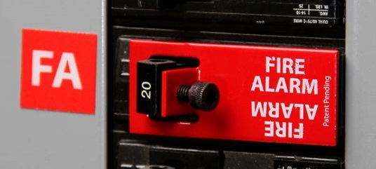
Fire alarm dedicated branch circuit breaker lock
Example of a locking device used to prevent unauthorized operation of a fire alarm branch-circuit breaker.

What About GFCI and AFCI Protection?

This subject is frequently oversimplified in fire alarm discussions.

Do not use the blanket rule that a fire alarm circuit can never have GFCI or AFCI protection. NEC requirements and exceptions must be evaluated based on the application, location, wiring method and adopted code edition.

Where AFCI or GFCI requirements would otherwise apply, review the applicable NEC article and fire alarm provisions carefully before determining whether an exception applies.

Fire Alarm Equipment and Circuit Identification

Fire alarm equipment supplying power-limited circuits must be identified so installers and service technicians can determine which circuits are power limited.

Proper identification becomes particularly important where power-limited and non-power-limited conductors enter the same fire alarm equipment enclosure.

Always follow the terminal markings, equipment listing and manufacturer's installation instructions when determining permitted conductor routing and separation inside equipment.

Fire Alarm Cable Support and Installation

Fire alarm cable should be installed in a neat and workmanlike manner and supported using methods suitable for the cable and installation environment.

Exposed fire alarm cable must be protected from physical damage and properly supported by the building structure or by an approved supporting method.

Do not use another raceway as a convenient support for fire alarm cable. Fire alarm cable should not simply be strapped to the exterior of conduit, piping or another raceway as a substitute for proper cable support.

Above suspended ceilings, fire alarm wiring should be independently supported in accordance with the applicable NEC requirements rather than resting on the ceiling grid or ceiling tiles.

Protecting Fire Alarm Cable From Nails and Screws

One of the most practical NEC requirements for installers involves protecting concealed cable from physical damage caused by nails and screws.

Where fire alarm cable passes through framing members near the edge of the framing, sufficient clearance must be maintained or an approved steel plate or equivalent mechanical protection must be installed where required.

This is especially important near:

  • Door frames
  • Baseboards
  • Drywall attachment points
  • Cabinetry
  • Wall-mounted equipment
  • Other locations where screws or nails can penetrate the framing
Steel protection plate protecting fire alarm cable in wall framing
Steel protection plate used to help protect concealed wiring from nails and screws.

Fire Alarm Cable Through Walls and Floors

Where fire alarm conductors pass through walls, floors or other areas where they can be exposed to physical damage, additional mechanical protection can be required.

The required protection depends on the wiring method, location and construction of the building.

Remember that mechanical protection and firestopping are two different issues.

A cable penetration through a rated wall or floor must maintain the required fire-resistance rating using an approved firestop system suitable for the penetration and construction assembly.

Fire alarm raceway penetration protected with listed firestop material
Example of a penetration protected with firestop material.
Listed firestop grommet for fire alarm cable penetration
Example of a listed firestop product designed for cable penetrations.

Fire Alarm Cable Separation From 120V and Power Wiring

Fire alarm cable separation is one of the most misunderstood portions of NEC Article 760.

Under the 2023 NEC Article 760 framework, power-limited fire alarm conductors generally cannot occupy the same cable, cable tray, compartment, enclosure, raceway, outlet box or similar fitting with electric light, power, Class 1, non-power-limited fire alarm and certain other higher-energy circuit conductors unless one of the permitted conditions applies.

Permitted arrangements can include installations using:

  • Listed or permitted barriers.
  • Separate raceways within an enclosure.
  • Associated-system provisions inside equipment.
  • Required conductor separation.
  • Other specific conditions permitted by the applicable NEC section.
Important: The familiar statement that fire alarm cable must always remain "2 inches from 120V" is an oversimplification. The NEC contains different rules depending on whether conductors are in raceways, enclosures, associated equipment or other permitted wiring arrangements.

PLFA Conductors Inside Fire Alarm Equipment

Power conductors and power-limited fire alarm conductors can sometimes enter the same equipment enclosure because both are required for connection to that equipment.

Where the NEC associated-system provisions are used, conductor routing and separation must comply with the applicable requirements. A commonly encountered requirement is maintaining separation between power-limited fire alarm conductors and higher-energy conductors within the enclosure unless another permitted protection method is used.

Always follow the fire alarm equipment manufacturer's internal wiring and separation instructions in addition to the NEC.

Class 1, Class 2 and Class 3 Circuits

Fire alarm technicians frequently encounter other limited-energy circuits in the same building, including security, access control, communications, HVAC controls and other signaling systems.

The fact that two circuits are both "low voltage" does not automatically mean they can share a raceway, enclosure or cable tray.

Class 1 Circuits

Class 1 circuits have different power and wiring characteristics from PLFA circuits. Where PLFA conductors are installed near Class 1 circuits, the applicable separation requirements must be followed.

Class 2 and Class 3 Circuits

Class 2 and Class 3 circuits are limited-energy circuits commonly encountered in control, signaling, communications and similar systems.

Whether PLFA conductors can share an enclosure, raceway, cable tray or routing assembly with these circuits depends on the circuit classification, conductor insulation, function and the specific NEC permission being used.

Do not use "it's all low voltage" as the installation rule.

Can Fire Alarm Wire Share Conduit With Other Low-Voltage Wiring?

Sometimes, but not automatically.

The answer depends on the classification of every circuit involved and the NEC rules applicable to those circuits.

Before combining fire alarm wiring with another system, determine:

  • Whether the fire alarm circuit is PLFA or NPLFA.
  • The classification of the other circuit.
  • Whether the circuits are functionally associated.
  • The insulation ratings of the conductors.
  • Whether the NEC specifically permits the circuits to occupy the same raceway or enclosure.
  • Whether the equipment listing or manufacturer prohibits the arrangement.

FPL, FPLR and FPLP Fire Alarm Cable

Power-limited fire alarm cable is marked according to its listing and permitted application.

FPL Cable

FPL is general-purpose power-limited fire alarm cable. Its use is limited to locations where a higher-rated riser or plenum cable is not required.

FPLR Cable

FPLR is riser-rated power-limited fire alarm cable intended for qualifying vertical applications and other locations where its listing permits its use.

FPLP Cable

FPLP is plenum-rated power-limited fire alarm cable and is suitable for applications requiring a plenum-rated fire alarm cable.

Fire Alarm Cable Substitutions

The NEC permits certain higher-rated cables to substitute for lower-rated power-limited fire alarm cables.

A useful hierarchy to remember is:

  • FPLP: CMP can be a permitted substitute.
  • FPLR: permitted substitutions can include CMP, FPLP and CMR.
  • FPL: permitted substitutions can include CMP, FPLP, CMR, FPLR, CMG and CM.

Important: Cable substitution requirements are an area being reorganized in newer NEC editions. Verify the applicable section in the NEC edition adopted for your project rather than relying solely on an older Article 760 section number.

Fire Alarm Conductor Size

Conductor size must comply with the applicable NEC requirements as well as the listing and installation instructions of the connected fire alarm equipment.

Smaller conductors can be permitted under specific listed conditions, while single conductors are subject to their applicable minimum-size requirements.

Remember that NEC minimum conductor size does not determine whether the wire is large enough for the actual fire alarm circuit.

Notification appliance circuits and other powered circuits must also be evaluated for voltage drop, current draw, circuit length and the fire alarm manufacturer's requirements.

For a complete calculation example, see our Fire Alarm Voltage Drop Calculator & NAC Calculation Guide.

Fire Alarm Conduit Fill

When fire alarm conductors are installed in raceway, conduit fill must comply with the applicable NEC Chapter 9 requirements.

Conduit fill depends on factors including:

  • Raceway type.
  • Raceway trade size.
  • Number of conductors or cables.
  • Conductor insulation type.
  • Conductor or cable dimensions.

The NEC Chapter 9 tables and applicable annex tables can be used to determine the permitted number of conductors for common raceway and conductor combinations.

Example: EMT Conduit Fill

The original example below uses EMT and 14 AWG THHN conductors. When using a conduit-fill table, make sure you select the correct raceway type, trade size and conductor insulation before reading the permitted quantity.

NEC EMT conduit fill table for fire alarm wiring
Example NEC conduit-fill table for EMT and individual conductors.

NEC Article 760 Field Checklist

  • Identify whether each fire alarm circuit is PLFA or NPLFA.
  • Verify the fire alarm power-source listing.
  • Verify the dedicated branch-circuit requirements.
  • Properly identify the fire alarm circuit and disconnecting means.
  • Follow manufacturer requirements for conductor routing inside equipment.
  • Use the correct FPL, FPLR or FPLP cable for the installation environment.
  • Support exposed fire alarm cable properly.
  • Do not support fire alarm cable from unrelated raceways or piping.
  • Protect wiring from nails, screws and other physical damage.
  • Properly firestop penetrations through rated assemblies.
  • Verify separation from electric light, power and Class 1 circuits.
  • Verify compatibility before combining PLFA with Class 2 or Class 3 circuits.
  • Verify conductor size against equipment listings and circuit requirements.
  • Calculate voltage drop where applicable.
  • Verify conduit fill for raceway installations.
  • Check the NEC edition adopted by the AHJ.

Frequently Asked Questions About Fire Alarm Wiring

What NEC article covers fire alarm wiring?

NEC Article 760 covers fire alarm system circuits. Other NEC articles can also apply depending on the power source, wiring method, circuit classification, building conditions and equipment involved.

What is the difference between PLFA and NPLFA?

PLFA means power-limited fire alarm circuit. NPLFA means non-power-limited fire alarm circuit. The classification affects the permitted wiring methods, conductor requirements and separation rules.

Can fire alarm wire be installed with 120V wiring?

Power-limited fire alarm wiring generally must be separated from electric light and power conductors unless a specific NEC permission applies, such as an approved barrier, raceway arrangement or associated-equipment condition.

Does fire alarm wire always have to be 2 inches away from power?

No. The commonly repeated "2-inch rule" does not describe every permitted NEC installation. Separation requirements depend on the circuit types, wiring methods, raceways, enclosures and specific NEC provisions involved.

Can fire alarm cable be strapped to conduit?

Fire alarm cable should not use unrelated raceway or piping as a substitute for its required structural support. Use approved cable-support methods appropriate for the installation.

What is the difference between FPL, FPLR and FPLP?

FPL is general-purpose power-limited fire alarm cable, FPLR is riser-rated fire alarm cable and FPLP is plenum-rated fire alarm cable. The required rating depends on where the cable is installed.

Can fire alarm wiring share conduit with other low-voltage wiring?

It can be permitted in certain situations, but "low voltage" alone is not enough to make the installation compliant. The classification, insulation, function and NEC requirements for each circuit must be evaluated.

Does the NEC determine fire alarm wire size?

The NEC establishes applicable conductor requirements, but circuit design must also consider equipment listings, manufacturer instructions, current draw, circuit length and voltage drop.


Related Fire Alarm Wiring Guides

Fire Alarm Voltage Drop Calculator & NAC Calculation Guide
How to Use a Multimeter for Fire Alarm Systems
Fire Alarm Ground Fault Troubleshooting
520 Hz Fire Alarm Requirements

Code Disclaimer: NEC requirements vary by adopted edition and jurisdiction. Always verify the locally adopted edition of NFPA 70, applicable amendments, fire alarm equipment listings, manufacturer instructions and AHJ requirements before final design or installation.

Tuesday, December 20, 2016

How to Use a Multimeter for Fire Alarm Troubleshooting

A digital multimeter is one of the most important troubleshooting tools a fire alarm technician can carry. Used correctly, it can help locate ground faults, shorts, opens, incorrect end-of-line resistance, voltage problems, polarity issues, excessive current draw, and many other fire alarm circuit problems.

This guide explains how to use a multimeter for fire alarm troubleshooting, including how to measure DC and AC voltage, resistance, continuity, end-of-line resistors, ground faults, current, capacitance, and polarity.

For the examples in this article, we will use the Fluke 117 True-RMS digital multimeter. The same basic principles apply to many quality digital multimeters, although button locations, ranges, input jacks, and available functions vary by model.

Safety First: Never measure resistance, continuity, diode condition, or capacitance on an energized circuit. De-energize the circuit and discharge stored energy before making these measurements. Live voltage and current measurements require additional precautions, properly rated equipment, appropriate PPE, and qualified personnel. Always follow your meter manufacturer's instructions and applicable electrical-safety procedures.

Why Fire Alarm Technicians Need a Good Multimeter

Fire alarm systems are supervised electrical systems. When something changes electrically, the fire alarm control panel often responds with an alarm, supervisory, or trouble condition.

A multimeter allows the technician to see what is actually happening on the circuit rather than simply guessing from the message displayed at the panel.

A multimeter can help a fire alarm technician check:

  • DC circuit voltage
  • AC voltage
  • End-of-line resistance
  • Continuity
  • Open circuits
  • Short circuits
  • Ground faults
  • Reverse polarity
  • Current draw
  • Capacitance
  • Intermittent electrical problems

Fluke 117 Multimeter for Fire Alarm Troubleshooting

The Fluke 117 is a True-RMS digital multimeter with the functions a fire alarm technician commonly needs, including:

  • AC and DC voltage
  • Resistance up to 40 MΩ
  • Continuity
  • AC and DC current
  • Capacitance
  • Frequency
  • Diode testing
  • MIN/MAX/AVG recording
  • Auto-V/LoZ
  • Non-contact AC voltage detection

You do not need a Fluke 117 specifically to troubleshoot fire alarm systems. What matters is using a quality meter appropriate for the electrical environment and understanding how to use its functions correctly.

Understanding the Multimeter Test Lead Jacks

Before worrying about the rotary dial, understand the test lead connections.

On a typical digital multimeter:

  • Black lead → COM
  • Red lead → V/Ω jack for voltage, resistance, continuity, diode and related measurements
  • Red lead → A jack when measuring current using the meter's amperage input
Critical Warning: After measuring current, move the red lead back out of the amperage jack before attempting a voltage measurement. Leaving the lead in the current jack and placing the probes across a voltage source can create a short circuit, blow the meter fuse, damage equipment, and create a serious safety hazard.

Multimeter Buttons Fire Alarm Technicians Should Know

HOLD

The HOLD button freezes the displayed reading. This can be useful when the meter is positioned where the display is difficult to see or when you want to capture a particular measurement.

MIN/MAX

MIN/MAX records changing measurements and allows the technician to see minimum and maximum values. On the Fluke 117, an average value is also available.

This can be particularly useful when investigating an intermittent voltage condition rather than staring at the meter waiting for the problem to occur.

RANGE

The Fluke 117 normally supports automatic ranging, allowing the meter to select an appropriate measurement range automatically.

The RANGE button can be used when manual ranging is desirable.

Yellow Function Button

The yellow button operates much like a secondary-function key. It selects the alternate yellow function associated with applicable rotary-switch positions.

Understanding Multimeter Symbols and Settings

The meter pictured above is a Fluke 115. Its basic measurement functions are similar to the Fluke 117, although the 117 adds functions such as Auto-V/LoZ and VoltAlert.

Quick Multimeter Reference for Fire Alarm Technicians

Meter Function Common Fire Alarm Use
DC Volts NAC, IDC, auxiliary power, detector power and battery troubleshooting
AC Volts Transformer input/output and other applicable AC-powered equipment
Ohms (Ω) EOL resistors, circuit resistance, grounds and shorts on de-energized circuits
Continuity Checking conductors, switches and obvious opens/shorts on de-energized circuits
DC Amps Measuring current draw where appropriate
Capacitance Specialized troubleshooting of capacitive components or circuit behavior
MIN/MAX Capturing intermittent voltage changes
Auto-V/LoZ Distinguishing actual AC/DC voltage from some high-impedance ghost-voltage conditions

How to Measure DC Voltage on a Fire Alarm Circuit

DC voltage is one of the most common measurements a fire alarm technician makes.

Examples include:

  • Notification appliance circuits (NACs)
  • Initiating device circuits (IDCs)
  • Auxiliary power
  • Conventional detector power
  • Remote power supplies
  • Fire alarm batteries

To measure DC voltage:

  1. Place the black lead in COM.
  2. Place the red lead in the V/Ω jack.
  3. Select DC volts.
  4. Place the probes across the two points being measured.
  5. Read the voltage displayed by the meter.

Voltage is measured across the circuit or component, meaning the meter is connected in parallel with the points being tested.

How a Multimeter Shows Fire Alarm Polarity

Polarity is extremely useful when troubleshooting DC fire alarm circuits.

With the red probe on the expected positive conductor and the black probe on the expected negative conductor, a normal positive voltage reading indicates the expected polarity.

If the meter displays a negative value, the polarity at the probes is reversed.

This becomes particularly useful when troubleshooting circuits that intentionally change polarity during alarm operation.

See our dedicated guide:

How to Read Reverse Polarity With a Multimeter

How to Measure Resistance on a Fire Alarm Circuit

Resistance measurements are extremely useful for checking:

  • End-of-line resistors
  • Field wiring resistance
  • Ground faults
  • Short circuits
  • Open circuits
  • Relay and switch contacts
Important: Resistance measurements must be made with the circuit de-energized. Never place a meter set to resistance across an energized fire alarm circuit.

To measure resistance:

  1. De-energize and isolate the circuit being tested.
  2. Place the black lead in COM.
  3. Place the red lead in the V/Ω jack.
  4. Select the Ω resistance function.
  5. Place the probes across the isolated circuit or component.
  6. Read the resistance.

How to Read an End-of-Line Resistor With a Multimeter

Fire alarm systems commonly supervise field circuits using an end-of-line resistor (EOL or EOLR).

Suppose the fire alarm panel expects a 4.7 kΩ EOL resistor.

With the circuit properly isolated and de-energized, a reading near the expected resistance suggests the meter can see the EOL resistance through the field circuit.

A dramatically different reading provides a clue:

  • OL or extremely high resistance: possible open circuit or missing EOL
  • Very low resistance: possible short or another low-resistance path
  • Incorrect resistance: wrong EOL value, parallel resistance, field device condition, wiring issue, or another circuit path

Do not assume that seeing the correct EOL resistance proves every device on the circuit is functioning correctly. It only tells you what resistance the meter sees from the point where you are testing.

What Does OL Mean on a Multimeter?

OL commonly indicates that the measured resistance is beyond the meter's available range or that there is no continuous electrical path between the probes.

When troubleshooting a disconnected fire alarm field circuit, an OL reading can therefore be a useful indication of an open conductor.

But context matters. OL means something very different when measuring resistance than it does when using certain other meter functions.

How to Check Continuity on Fire Alarm Wiring

Continuity mode is a fast way to determine whether a low-resistance electrical path exists between two points.

On the Fluke 117, the continuity beeper turns on below approximately 20 Ω and turns off above approximately 250 Ω.

That is important because:

A continuity beep does not mean the circuit has zero resistance.

It simply means the measured resistance meets the meter's continuity threshold.

When the actual resistance value matters, switch to the Ω function and read the resistance rather than relying solely on the beep.

How to Find a Short Circuit With a Multimeter

With a fire alarm circuit properly de-energized and isolated, an unexpectedly low resistance between conductors can indicate a short or another unintended electrical path.

However, connected field devices, EOL components, relays, modules, surge-protection components and other equipment can affect resistance readings.

For that reason, isolate portions of the circuit methodically rather than assuming every low-resistance reading means two bare conductors are touching.

How to Find a Fire Alarm Ground Fault With a Multimeter

A ground fault occurs when a normally isolated fire alarm conductor develops an unintended electrical connection to ground or another grounded conductive surface.

A multimeter set to resistance can be extremely useful for locating the affected conductor once the circuit is safely isolated.

One common troubleshooting approach is to:

  1. Identify the affected circuit.
  2. Disconnect and isolate the field conductors according to proper service procedures.
  3. Verify the circuit is de-energized before making resistance measurements.
  4. Measure each conductor to ground.
  5. Divide the circuit into sections.
  6. Repeat the measurement until the affected section is isolated.

For the complete process, see our dedicated guide:

Fire Alarm Ground Fault Troubleshooting | How to Find a Ground Fault

Why High Resistance Matters When Troubleshooting Ground Faults

Not every ground fault is a dead short to ground.

Moisture, damaged insulation, contaminated equipment, deteriorated cable and other conditions can create a high-resistance or intermittent path to ground.

This is one reason a meter with a useful resistance range matters. The Fluke 117 can measure resistance up to 40 MΩ.

Remember, however, that the fire alarm panel's ground-fault detection circuitry and your handheld meter are not identical instruments. A resistance reading from the meter must be interpreted in the context of the system you are troubleshooting.

Using Auto-V/LoZ to Identify Ghost Voltage

The Fluke 117 includes an Auto-V/LoZ function.

Auto-V automatically determines whether the applied voltage is AC or DC, while the low-input-impedance function helps reduce misleading readings caused by capacitively coupled or so-called ghost voltage.

This can be useful when a high-impedance digital meter displays a voltage on a conductor that cannot actually sustain meaningful current.

Do not use LoZ indiscriminately on sensitive electronic circuits. Understand the circuit and the meter function before applying it.

How to Measure Current on a Fire Alarm Circuit

Current measurement is fundamentally different from measuring voltage.

Voltage is normally measured across two points.

Current is measured by placing the meter in series with the circuit so current flows through the meter.

Use Extra Caution: Measuring current incorrectly can blow the meter fuse, damage equipment, or create a short circuit. Verify the meter's current rating, fuse, lead position, circuit current, and manufacturer's instructions before attempting an amperage measurement.

For a typical current measurement:

  1. Determine whether the expected current is within the meter's rating.
  2. Move the red lead to the appropriate current input jack.
  3. Select AC or DC current as appropriate.
  4. Open the circuit at the proper test point.
  5. Connect the meter in series so circuit current flows through the meter.
  6. Take the measurement.
  7. Remove the meter safely.
  8. Return the red lead to the V/Ω jack when finished.

See the dedicated article:

How to Measure Electrical Current With a Multimeter

Using MIN/MAX for Intermittent Fire Alarm Problems

Some of the most frustrating fire alarm problems disappear the moment the technician arrives.

MIN/MAX recording can help capture voltage excursions that occur while you are monitoring a circuit.

For example, if auxiliary power occasionally dips during equipment operation, MIN/MAX can help determine how low the voltage dropped even if you did not happen to be watching the display at that exact moment.

This does not replace proper diagnostic equipment or event-history analysis, but it can be extremely useful during field troubleshooting.

Can a Multimeter Measure Fire Alarm Voltage Drop?

Yes, but there is an important distinction between measuring actual voltage at points on an operating circuit and calculating expected voltage drop during system design.

A technician can measure voltage at the power source and at a downstream point under the appropriate operating condition to evaluate actual circuit performance.

A designer can calculate expected voltage drop using conductor resistance, circuit length and load.

For the complete design process, see:

Fire Alarm Voltage Drop Calculator & NAC Calculation Guide

Common Multimeter Mistakes in Fire Alarm Troubleshooting

  • Measuring resistance on an energized circuit. Resistance and continuity testing require a de-energized circuit.
  • Leaving the red lead in the amperage jack. This can create a short when the technician later attempts a voltage measurement.
  • Using continuity mode as a precision resistance test. A beep only indicates the meter's continuity threshold has been met.
  • Assuming OL always means the same thing. Interpret the display according to the selected meter function.
  • Testing a circuit without isolating connected equipment. Parallel components can dramatically affect resistance readings.
  • Assuming every unexpected voltage is real usable voltage. High-impedance meters can sometimes display capacitively coupled ghost voltage.
  • Assuming the meter caused the polarity reversal. The negative sign simply indicates the polarity at the probes is opposite the selected reference.
  • Using the wrong meter category or damaged leads. Inspect the meter and leads and use equipment properly rated for the electrical environment.

Fire Alarm Multimeter Troubleshooting Cheat Sheet

What Are You Looking For? Meter Function
DC fire alarm circuit voltage DC Volts
AC power AC Volts
EOL resistor value Ohms
Open conductor Ohms / Continuity
Shorted conductors Ohms / Continuity
Conductor leaking to ground Ohms
DC polarity DC Volts
Current draw DC or AC Amps
Intermittent voltage change MIN/MAX
Possible ghost voltage Auto-V/LoZ where appropriate

Frequently Asked Questions

What multimeter setting should I use for a fire alarm circuit?

It depends on what you are testing. Use DC volts for most powered DC fire alarm circuits, AC volts for applicable AC power, and resistance or continuity only after the circuit has been properly de-energized and isolated.

How do I check a fire alarm EOL resistor?

De-energize and properly isolate the circuit, set the meter to resistance (Ω), and measure across the resistor or isolated circuit. Compare the reading with the resistance specified by the fire alarm equipment manufacturer.

How do I check a fire alarm wire for a ground fault?

After safely isolating and de-energizing the affected field circuit, resistance measurements from each conductor to ground can help identify an unintended path to ground. Divide the circuit into sections until the affected wiring or device is located.

What does a negative voltage reading mean?

On a DC voltage measurement, a negative reading generally means the polarity at the probes is opposite the meter's reference orientation. Reversing the probes will reverse the sign of the displayed voltage.

What does OL mean when checking fire alarm wiring?

When measuring resistance, OL generally indicates an open electrical path or resistance beyond the meter's available measurement range.

Can I measure resistance on a powered fire alarm circuit?

No. De-energize the circuit before measuring resistance or continuity. External voltage can produce invalid readings and can damage the meter or create a safety hazard.

Can I use continuity mode to find a fire alarm short?

Continuity mode can quickly identify a low-resistance path on a properly de-energized and isolated circuit. However, connected devices and components can affect the reading, so use the actual resistance measurement when more precise information is required.

Can I use a multimeter to troubleshoot a NAC?

Yes. A multimeter can help evaluate NAC voltage, polarity, resistance, continuity and field wiring. Always consider whether the circuit changes polarity or operating condition during alarm and follow the fire alarm equipment manufacturer's instructions.

What is the best multimeter for a fire alarm technician?

A good fire alarm multimeter should provide reliable AC/DC voltage, resistance, continuity and current measurements and be properly rated for the electrical environments in which it will be used. Additional features such as MIN/MAX, capacitance and low-impedance voltage measurement can be useful. The Fluke 117 used in this article is one example, but many professional meters can perform the required work.

Related Fire Alarm Troubleshooting Guides

Final Thoughts

A multimeter becomes far more valuable when a fire alarm technician understands what the reading actually means.

Voltage tells you electrical potential between two points. Resistance helps identify circuit resistance, EOL values, opens, shorts and leakage paths on properly de-energized circuits. Continuity provides a quick indication of a low-resistance path. Current tells you how much electrical current is flowing through a circuit when measured correctly in series.

The meter does not troubleshoot the fire alarm system for you. It gives you electrical evidence.

The technician's job is to combine that evidence with the fire alarm panel's indications, circuit architecture, sequence of operation, equipment documentation and a systematic troubleshooting process.

Safety and Technical Disclaimer: This article is intended for qualified fire alarm and electrical professionals. Always follow the multimeter manufacturer's instructions, equipment documentation, applicable electrical-safety requirements, employer procedures and adopted codes. De-energize circuits whenever possible and never perform resistance, continuity, diode or capacitance measurements on energized circuits.

Elevator Shunt Trip Wiring Diagram | Fire Alarm Power Shutdown

An elevator shunt trip is used to automatically disconnect elevator power when required by the approved elevator and fire protection design, typically where sprinkler operation could create an unsafe condition for elevator equipment.

The fire alarm system commonly provides the initiating interface for this function through heat detection and listed control equipment.

This guide explains the basic elevator shunt trip wiring sequence, the purpose of the heat detector, fire alarm control relay, shunt-trip disconnect, power monitoring, and how elevator recall differs from elevator power shutdown.

Important: The diagram below is a typical educational example, not a universal construction detail. Elevator power shutdown must follow the adopted elevator code, NFPA 72, NFPA 13 where applicable, electrical requirements, equipment listings, approved plans, elevator manufacturer's requirements, and the AHJ-approved sequence of operations.

Elevator Shunt Trip Wiring Diagram

The diagram above illustrates a typical concept for interfacing a fire alarm system with an elevator shunt-trip disconnect.

The exact arrangement varies by project. Always use the approved project drawings and equipment-specific wiring diagrams rather than treating a generic diagram as a universal installation detail.

What Is an Elevator Shunt Trip?

An elevator shunt trip is a means of automatically disconnecting electrical power to elevator equipment when required by the elevator/fire protection design.

The objective is not simply to "turn the elevator off."

Where the applicable elevator code requires automatic power shutdown because sprinkler water could create an unsafe elevator condition, the shutdown must occur upon or prior to the application of water.

The fire alarm system commonly interfaces with the electrical disconnect through a control relay or other listed interface equipment.

Elevator Recall and Elevator Shunt Trip Are Different Functions

This distinction is extremely important.

Elevator recall and elevator power shutdown are separate emergency-control functions.

Function Typical Purpose
Elevator Recall Causes the elevator system to respond to a fire alarm recall signal and move according to the approved recall sequence.
Elevator Shunt Trip Disconnects applicable elevator power when automatic power shutdown is required.

A smoke detector used for elevator recall should therefore not be confused with a heat detector used to initiate elevator power shutdown.

Basic Elevator Shunt Trip Sequence

A typical elevator shunt-trip sequence can be understood as:

Heat Detector → Fire Alarm System → Control Relay → Shunt-Trip Disconnect → Elevator Power Removed

The actual system may contain additional monitoring modules, relays, power supplies, disconnects, elevator-controller interfaces, and other components.

Each component serves a specific function and must be coordinated with the approved sequence of operations.

Why Is a Heat Detector Used for Elevator Shunt Trip?

Where automatic elevator power shutdown is required in connection with sprinkler protection, heat detection is commonly used to initiate the shutdown function before sprinkler water is discharged onto elevator equipment.

The purpose is timing.

The shutdown arrangement must coordinate the initiating device and sprinkler so the required power disconnect occurs upon or before water application.

This is different from elevator recall, which is commonly initiated by smoke detection in designated elevator-related locations.

Heat Detector Location Near the Sprinkler

Where heat detection is used to initiate elevator power shutdown, the detector location and temperature characteristics must be coordinated with the sprinkler installation and applicable requirements.

The commonly encountered arrangement places the heat detector within the required proximity of the associated sprinkler so that the detector can respond in time to initiate the shutdown sequence.

Do not simply install one heat detector somewhere in an elevator machine room and assume the requirement has been satisfied. The detector arrangement must correspond with the sprinkler protection and approved design.

Heat Detector Temperature Rating and Sprinkler Temperature

The temperature characteristics of the heat detector and sprinkler are critical.

The goal is for the elevator shutdown sequence to operate before sprinkler discharge when the applicable design requires power removal before water is applied to elevator equipment.

For this reason, the heat detector selection cannot be treated independently from the sprinkler temperature classification and response characteristics.

Design Point: Never select the elevator shunt-trip heat detector solely because a particular temperature rating is normally stocked. Coordinate the detector with the sprinkler and the approved elevator shutdown design.

Fire Alarm Relay for Elevator Shunt Trip

The fire alarm system commonly controls the elevator shunt-trip function through a listed control relay or control module.

When the appropriate heat detector activates, the fire alarm system changes the state of the control output according to the programmed sequence.

That interface then operates the shunt-trip circuit associated with the elevator disconnect.

The exact relay contact configuration, control voltage, wiring method, and fail-safe arrangement depend on the equipment and approved design.

Never assume that normally open or normally closed is universally correct for every shunt-trip installation.

Need the detailed wiring method? For a deeper explanation of ECID placement, supervised control wiring, addressable relay modules, FCM-1 versus FRM-1 operation and external interface relays, see our How to Wire an Elevator Shunt Trip | ECID & Relay Supervision guide.

What Does the Shunt-Trip Breaker or Disconnect Do?

A shunt-trip mechanism allows a circuit breaker or disconnecting means to be electrically operated from a remote signal.

In an elevator power-shutdown application, activation of the required interface causes the applicable elevator power to be disconnected.

The fire alarm control equipment is therefore generally providing the control signal. It is not carrying the elevator motor power through the fire alarm relay.

Critical: Elevator power must never be routed directly through ordinary fire alarm relay contacts unless the equipment is specifically listed and rated for that application. The fire alarm interface normally controls the appropriate listed shunt-trip equipment.

Why Shunt-Trip Control Power Matters

A shunt-trip mechanism needs an available source of control power in order to operate.

That creates an important supervision question:

What happens if the shunt-trip control power is lost before a fire occurs?

If the power necessary to perform the required shutdown is unavailable, the fire alarm system needs to provide the required indication of that impairment where required by the applicable system design and code.

This is why elevator shunt-trip installations commonly include monitoring associated with the availability of the control power.

Monitoring Shunt-Trip Power

A properly designed system should not silently lose the power necessary to perform a required elevator shutdown function.

Depending on the design, the fire alarm system may monitor the availability of the shunt-trip control power through an approved supervisory interface.

If that power becomes unavailable, the fire alarm system can then indicate the abnormal condition rather than leaving a hidden impairment.

The exact monitoring arrangement depends on the disconnect, control-power source, fire alarm equipment, approved plans, and applicable adopted requirements.

What Happens When the Shunt-Trip Heat Detector Activates?

A typical sequence is:

  1. The elevator-area heat detector reaches its operating point.
  2. The fire alarm control unit receives the detector input.
  3. The fire alarm system activates the programmed elevator power-shutdown output.
  4. The associated fire alarm control relay or module changes state.
  5. The shunt-trip mechanism operates.
  6. The applicable elevator power is disconnected.
  7. The fire alarm system provides the required event indications according to the approved sequence.

The actual project sequence may contain additional operations and must always be verified against the approved input/output matrix.

Should Elevator Recall Happen Before Shunt Trip?

Elevator recall and power shutdown are coordinated functions, but technicians should be careful with the common field explanation that the fire alarm system simply "recalls the elevator first and then waits to shunt it."

The power-shutdown function is governed by the required response to the sprinkler hazard and the approved elevator-system design.

Do not create an arbitrary fire alarm timer intended to delay required elevator power shutdown unless that exact arrangement is permitted by the applicable codes, elevator equipment, and approved design.

The fire alarm system should execute the approved sequence rather than improvising a delay in the field.

Smoke Detector vs. Heat Detector for Elevator Functions

Device Common Elevator Function
Smoke Detector Elevator recall and related Phase I emergency operation inputs where required.
Heat Detector Elevator power shutdown where required in coordination with sprinkler protection.
Waterflow Reports sprinkler waterflow but should not automatically be assumed to be the initiating input for the elevator shunt-trip function.

Does Sprinkler Waterflow Shunt Trip the Elevator?

Do not automatically use the sprinkler waterflow switch as the elevator shunt-trip initiating device simply because the shutdown is associated with sprinkler protection.

The purpose of the elevator power-shutdown arrangement is to disconnect the required power upon or prior to the application of water where the elevator code requires that protection.

Waiting for established sprinkler waterflow can be inconsistent with that objective.

Follow the approved heat-detection and shutdown design for the project.

Elevator Machine Room Shunt Trip

Where sprinklers are installed in an elevator machine room, machinery space, control room, control space, hoistway, or other applicable elevator equipment area, the designer must determine whether elevator power shutdown is required by the adopted elevator code and project conditions.

The answer should not be based simply on the fact that the building has elevators or sprinklers.

Modern elevator and sprinkler requirements contain important exceptions and installation options, so each project needs to be evaluated under its adopted codes and elevator design.

Elevator Pit Sprinklers and Shunt Trip

Elevator pits deserve particular attention because the presence of a sprinkler does not automatically mean every pit requires identical fire alarm shutdown equipment.

The sprinkler arrangement, elevator equipment exposure, applicable elevator-code provisions, and approved design determine the required sequence.

Never copy the machine-room shunt-trip design into the pit without verifying the requirements for that specific elevator installation.

NFPA 72 and Elevator Power Shutdown

NFPA 72 addresses the fire alarm system's role in emergency control function interfaces, including elevator-related functions.

The fire alarm system may be responsible for receiving the appropriate initiating-device input, processing the programmed sequence, operating listed control interfaces, supervising applicable pathways or functions, and annunciating abnormal conditions.

However, NFPA 72 is not the only standard involved.

Elevator shunt trip can involve requirements from:

  • NFPA 72, National Fire Alarm and Signaling Code
  • The adopted elevator safety code, commonly based on ASME A17.1/CSA B44
  • NFPA 13 where sprinkler protection is involved
  • NFPA 70 / NEC for electrical installation requirements
  • The adopted building and fire codes
  • Elevator manufacturer requirements
  • Fire alarm equipment listings and instructions
  • The Authority Having Jurisdiction

Do Not Treat the Fire Alarm Diagram as the Complete Elevator Design

A fire alarm drawing may show a heat detector, control module, monitor module, and interface to the elevator disconnect.

That does not necessarily document every part of the elevator electrical installation.

Coordination may be required between:

  • Fire alarm contractor
  • Elevator contractor
  • Electrical contractor
  • Sprinkler contractor
  • Mechanical contractor
  • Engineer of record
  • Fire alarm designer
  • Elevator inspector
  • Fire marshal or other AHJ

Elevator shunt trip is one of those deceptively small details on a fire alarm drawing that can involve several trades.

Testing an Elevator Shunt-Trip Interface

Testing should verify the complete approved sequence rather than merely checking whether a relay LED turns on.

Depending on the project and applicable requirements, coordinated testing should verify items such as:

  • Correct initiating heat detector
  • Correct fire alarm input identification
  • Correct programmed output
  • Operation of the fire alarm control relay or module
  • Operation of the approved elevator power-shutdown interface
  • Required monitoring of control power
  • Correct annunciation at the fire alarm control unit
  • Restoration of the system after testing
  • Coordination with elevator recall and other elevator emergency functions
Testing Warning: Do not intentionally remove elevator power during testing without coordination with the elevator contractor, building representative, and other responsible parties. An uncontrolled shunt-trip test can trap occupants, interrupt building operations, or create equipment and safety problems.

Common Elevator Shunt Trip Wiring Mistakes

  • Confusing recall with shunt trip. They are separate elevator emergency functions.
  • Using the wrong initiating device. Smoke detection and heat detection commonly perform different elevator functions.
  • Using waterflow as the automatic shutdown trigger without verifying the design.
  • Failing to coordinate the heat detector with the sprinkler installation.
  • Ignoring loss of shunt-trip control power.
  • Using an arbitrary software timer to delay shutdown.
  • Assuming every elevator pit or machine room has the same requirements.
  • Using a generic wiring diagram instead of the approved project documents.
  • Failing to coordinate fire alarm, elevator, electrical and sprinkler trades.
  • Testing the fire alarm relay but not the complete integrated function.

Elevator Shunt Trip Quick Reference

Primary Purpose Automatic elevator power shutdown where required
Typical Initiating Device Heat detector associated with applicable sprinkler protection
Fire Alarm Output Listed control relay/module or other approved interface
Controlled Equipment Approved elevator shunt-trip disconnecting means
Separate From Elevator recall
Important Coordination Elevator, fire alarm, sprinkler and electrical systems

Frequently Asked Questions

What is an elevator shunt trip?

An elevator shunt trip is an automatic means of disconnecting applicable elevator electrical power when required by the approved elevator and fire-protection design.

What activates an elevator shunt trip?

Where power shutdown is required in coordination with sprinkler protection, heat detection is commonly used to initiate the fire alarm control sequence that operates the approved shunt-trip interface.

Does a smoke detector shunt trip an elevator?

Smoke detectors are commonly associated with elevator recall functions rather than the sprinkler-related power-shutdown function. The exact operation must follow the approved elevator and fire alarm sequence.

Does a sprinkler waterflow switch shunt trip an elevator?

Waterflow should not automatically be assumed to be the correct initiating input. Where shutdown is required upon or prior to sprinkler water application, the approved design commonly uses heat detection coordinated with the sprinkler rather than waiting for established waterflow.

Is elevator recall the same as elevator shunt trip?

No. Recall commands the elevator system to perform its approved emergency recall operation. Shunt trip disconnects applicable elevator power when power shutdown is required.

Does every elevator require shunt trip?

No. Whether automatic power shutdown is required depends on the elevator equipment, sprinkler protection, adopted elevator code, building conditions, and approved design.

Does every sprinkler in an elevator area require a heat detector?

Not automatically. The required detection and shutdown arrangement depends on whether automatic elevator power shutdown is required for that sprinkler/elevator condition under the applicable codes and approved design.

Why is shunt-trip power monitored?

If electrical power necessary to operate a required shunt-trip function is lost, the shutdown function can become impaired. Where required, monitoring allows that abnormal condition to be reported rather than remaining hidden.

Can the fire alarm relay directly switch elevator motor power?

Ordinary fire alarm control contacts are generally used to interface with the approved elevator power-shutdown equipment, not to carry elevator motor power. Always follow the equipment listings and approved electrical design.

Related Elevator Fire Alarm Guides

Final Thoughts

The key to understanding elevator shunt-trip wiring is recognizing that the fire alarm system is only one part of an integrated elevator power-shutdown function.

The heat detector provides the initiating condition. The fire alarm system processes that condition and operates the approved control interface. The shunt-trip equipment disconnects the required elevator power.

Meanwhile, elevator recall remains a separate emergency function with its own initiating devices and sequence.

For a successful installation, the fire alarm, elevator, sprinkler and electrical designs all have to agree on the same sequence of operation.

Technical Disclaimer: This article is intended for educational use by qualified fire alarm and life-safety professionals. Elevator power shutdown is an integrated life-safety function. Always follow the adopted codes and standards, approved construction documents, elevator manufacturer requirements, equipment listings, electrical-safety procedures, and AHJ requirements for the specific installation.

Saturday, September 5, 2015

Fire Alarm Ground Fault Troubleshooting | How to Find a Ground Fault

HOW TO FIND A FIRE ALARM GROUND FAULT

Fire alarm ground fault troubleshooting is easiest when you stop chasing individual devices and systematically isolate the affected wiring.

The basic process: identify the affected circuit, safely isolate the field wiring, test the conductors to ground, divide the circuit approximately in half, determine which half still contains the fault, and continue dividing until you locate the physical problem.

Hard grounds are often easy to find with a standard multimeter. Soft, high-resistance and intermittent ground faults caused by moisture, damaged insulation or contamination can be considerably harder to locate.

Of all the trouble conditions a fire alarm technician can receive, few have the ability to consume an entire service call quite like a fire alarm ground fault.

Some take five minutes to find.

Others appear after it rains, disappear when you open a junction box, return when the temperature changes, or show up on the fire alarm control panel while your multimeter seems convinced that absolutely nothing is wrong.

I originally wrote this article in 2015 after personally building the custom fire alarm ground fault meter shown below at home and then using it successfully on actual fire alarm service calls.

The reason I built it was simple: I was encountering soft and intermittent ground faults that the fire alarm control panel could detect but that were difficult to see clearly with the ordinary multimeter I was using.

This updated guide preserves the original meter, photographs, measurements and build process, but expands the article into a complete step-by-step guide explaining how to find a ground fault on a fire alarm system, how to troubleshoot SLC, NAC, IDC and power wiring, why soft grounds can be difficult to detect, and how the original FireAlarmsOnline custom tester works.

Fire Alarm Ground Fault Troubleshooting in 7 Steps

  1. Record the exact ground-fault trouble at the FACP.
  2. Check panel history, weather conditions and recent construction or service work.
  3. Identify the affected SLC, NAC, IDC, auxiliary-power or other field circuit.
  4. Safely isolate the affected field wiring according to the manufacturer's procedures.
  5. Test each isolated conductor to an appropriate known ground.
  6. Divide the faulted circuit approximately in half and determine which half contains the ground.
  7. Continue halving the faulted section until you locate and repair the physical problem.

That is the basic troubleshooting process.

If you are standing in front of a fire alarm panel with a ground-fault trouble right now, start there.

The rest of this guide explains why the process works, how to recognize different types of grounds, where to look first, and what to do when the panel detects a ground that your ordinary meter cannot easily find.

What Is a Ground Fault on a Fire Alarm System?

Most fire alarm field wiring is intended to remain electrically isolated from earth ground except where grounding is specifically part of the listed system design.

A fire alarm ground fault occurs when a normally isolated circuit conductor develops an unintended conductive path to earth ground, grounded conduit, a metal backbox, building steel, an enclosure or another grounded surface.

That unwanted path can be almost a dead short or it can have enough resistance that the connection is much harder to identify.

A fire alarm control unit supervises the system for abnormal conditions, including applicable ground faults. The exact ground-detection circuitry, voltage, resistance threshold and diagnostic capabilities vary by manufacturer and control unit.

IMPORTANT:

Do not assume every FACP detects ground faults using the same voltage or resistance threshold. The specific panel manufacturer's service documentation should always be part of the troubleshooting process.

Ground Fault vs. Short Circuit vs. Open Circuit

These three conditions are sometimes confused, but they are electrically different.

A ground fault is an unintended conductive path between a circuit conductor and ground.

A short circuit is generally an unintended conductive path between circuit conductors.

An open circuit occurs when the intended circuit path is broken.

A ground fault can exist while the affected fire alarm circuit continues to operate, which is one reason the condition should never be ignored simply because the devices still appear to function normally.

Why Fire Alarm Ground Faults Matter

A ground-fault trouble is not simply an annoying yellow light that needs to disappear before the technician can leave.

Applicable fire alarm pathways are supervised for abnormal conditions because an existing ground can create a situation where an additional fault could interfere with normal system operation.

The goal is not merely to clear the panel. The goal is to locate and repair the unwanted electrical connection.

Hard Ground vs. Soft Ground vs. Intermittent Ground Fault

1. Hard Ground Fault

A hard ground fault is a relatively low-resistance connection between a fire alarm conductor and ground.

Common causes include:

  • A conductor pinched against a grounded metal backbox
  • Insulation cut by a sharp knockout or fitting
  • Too much insulation stripped from a conductor
  • A loose conductor strand touching an enclosure
  • Wire trapped beneath a device or cover
  • Damaged cable contacting grounded conduit
  • A screw or fastener penetrating cable insulation

These are normally the easiest ground faults to locate because a standard resistance measurement can often reveal a relatively obvious path to ground.

2. Soft or High-Resistance Ground Fault

A soft ground fault is common field terminology for a more resistive leakage path to ground.

Instead of bare copper making solid contact with grounded metal, the electrical path might involve moisture, contamination, deteriorated insulation, corrosion or another high-resistance path.

These faults can be particularly frustrating because the FACP can sometimes detect the ground while a conventional handheld meter does not reproduce the condition as clearly.

3. Intermittent Ground Fault

An intermittent fire alarm ground fault appears and disappears.

Common causes include:

  • Water entering an outdoor notification appliance or backbox
  • Condensation
  • Temperature changes
  • Vibration
  • Loose conductor strands
  • Damaged insulation that contacts metal only when moved
  • Expansion or contraction of conduit and wiring
  • Corroded terminations

Intermittent grounds can be among the most difficult fire alarm troubles because the fault may disappear while you are trying to locate it.

Where Do Fire Alarm Ground Faults Usually Occur?

Before opening every junction box in the building, think about the environment and what has recently changed.

Pay particular attention to:

  • Outdoor horn/strobes and other weather-exposed equipment
  • Exterior backboxes
  • Parking garages
  • Rooftop equipment
  • Elevator pits
  • Mechanical rooms
  • Damp electrical rooms
  • Underground and exterior raceways
  • Recently replaced devices
  • Recently remodeled areas
  • Sharp metal knockouts
  • Crowded junction boxes
  • Shield and drain wires
  • Splices exposed to moisture
  • Cable that has been pulled, crushed or pinched
FIELD TIP: ASK WHAT CHANGED.

Did construction happen yesterday?
Did it rain last night?
Was an elevator serviced?
Did someone replace a horn/strobe?
Did another trade open a junction box?

A good fire alarm technician troubleshoots the building as well as the wiring.

How to Find a Ground Fault on a Fire Alarm System

Step 1: Read the FACP Before Disconnecting Anything

Document the exact trouble condition.

Check the event display, circuit information, diagnostic indicators and system history when available.

Some fire alarm systems provide useful information about the affected circuit or polarity of the ground.

Do not reset the panel or begin randomly disconnecting wires before recording what the system is telling you.

Step 2: Check the Manufacturer's Ground-Fault Troubleshooting Procedure

Before removing field wiring, consult the service documentation for the specific FACP.

Modern addressable systems can provide diagnostic information that may dramatically reduce troubleshooting time.

Step 3: Identify the Affected Fire Alarm Circuit

A ground fault can involve:

  • SLC wiring
  • NAC wiring
  • IDC wiring
  • Auxiliary power
  • Remote power supplies
  • Control circuits
  • Communicator wiring
  • Shield or drain conductors
  • Remote equipment

The exact isolation procedure depends on the system architecture and manufacturer.

Step 4: Isolate One Logical Circuit at a Time

Follow the manufacturer's procedures and applicable impairment/testing requirements.

Avoid removing several circuits simultaneously unless the troubleshooting procedure specifically requires it. Disconnecting too much at once can destroy the cause-and-effect information you are trying to obtain.

Step 5: Confirm Which Branch Contains the Ground

When removing or isolating a branch causes the ground indication to clear, you have narrowed the problem.

Where appropriate, reconnecting the branch and confirming that the ground returns can provide additional evidence that you are following the correct wiring.

Step 6: Divide the Faulted Circuit in Half

Once the affected field wiring has been safely identified and isolated, locate a convenient point approximately halfway through the circuit.

Separate the circuit there and determine which half still contains the unwanted path to ground.

Step 7: Keep Dividing the Faulted Half

Go approximately halfway through the remaining faulted section and repeat the process.

FIND THE BAD HALF → DIVIDE IT → FIND THE BAD HALF → DIVIDE AGAIN

This half-split or divide-and-conquer method is usually much faster than checking every device sequentially from the panel to the end of a large circuit.

How to Use a Multimeter to Find a Fire Alarm Ground Fault

For appropriately isolated and de-energized field wiring, a resistance measurement between each conductor and an appropriate known ground can help identify an unwanted leakage path.

A healthy isolated conductor should not show an unintended conductive connection to ground.

A hard ground may produce a relatively low resistance reading.

A soft ground may appear as a much higher resistance, an unstable reading or a condition that changes with moisture, movement or time.

For a complete explanation of meter functions, see our guide to using a multimeter for fire alarm troubleshooting.

Why Does the Fire Alarm Panel See a Ground Fault but My Multimeter Doesn't?

This question is the reason I originally built the FireAlarmsOnline custom ground-fault tester.

The FACP and your handheld meter do not necessarily test the wiring under identical electrical conditions.

A handheld ohmmeter uses its own internal battery and measurement circuitry. The fire alarm control unit uses its own ground-supervision circuitry. The applied test conditions and detection thresholds can therefore be different.

Some high-resistance leakage paths can also behave differently under different applied test potentials.

That means a soft or intermittent ground can sometimes be apparent to the FACP while being considerably less obvious with the particular handheld meter being used.

IMPORTANT TECHNICAL DISTINCTION:

Higher voltage does not magically reveal every ground fault, and more voltage is not automatically better.

My field experience with the original tester was that certain high-resistance and intermittent leakage paths became easier to identify under its different, higher test potential.

The appropriate test voltage always depends on the isolated wiring and equipment manufacturer's requirements.

The Original FireAlarmsOnline Custom Soft Ground Fault Tester

This is the part of the article that started everything.

I personally built the meter shown below at home in my kitchen and later used it successfully in the field.

The goal was to create a portable troubleshooting tool with a higher test potential than the ordinary analog ohmmeter I was using, making certain difficult soft and intermittent fire alarm ground faults easier to identify.

Original Analog Ohmmeter Output

Before modifying anything, I measured the output of the analog ohmmeter used for the prototype.

That particular meter measured approximately 1.628 VDC under the test conditions used for the original experiment.

Original FireAlarmsOnline prototype measurement showing approximately 1.628 VDC from the analog ohmmeter before the custom ground-fault tester was built.

Safety Warning Before Building or Using the Custom Tester

IMPORTANT ELECTRICAL AND EQUIPMENT SAFETY WARNING

This custom tester applies a higher external DC test potential than an ordinary resistance meter.

Never connect this tester to an energized fire alarm circuit.

Before applying an external test voltage, the wiring being tested must be appropriately isolated from the FACP and electronic equipment that could be damaged or affected by the test.

Depending on the circuit, this can include control boards, power supplies, addressable devices, modules, notification appliances, communicators, surge-protection components and other electronic equipment.

Follow the equipment manufacturer's published testing instructions and voltage limitations.

Do not assume approximately 36 to 40 VDC is safe for every connected fire alarm device simply because it worked with the isolated wiring conditions used for my original prototype.

Parts Used to Build the Original Fire Alarm Ground Fault Tester

Original components used to build the FireAlarmsOnline custom ground-fault troubleshooting meter.

The original prototype used:

  • 1 analog ohmmeter
  • 4 nine-volt batteries
  • 4 nine-volt battery connectors with flying leads
  • Ohmmeter test leads
  • A properly selected series resistor
  • Heat-shrink tubing
  • Velcro straps
  • A digital multimeter for verification measurements
  • Soldering equipment
  • Wire strippers and normal electrical hand tools
DO NOT AUTOMATICALLY COPY THE 2.2 kΩ RESISTOR VALUE.

The 2.2 kΩ resistor was selected for the particular analog meter and measurements used in my original prototype.

Different analog meters can have different internal resistance, battery voltage, meter-movement characteristics and current requirements.

How to Build the Custom Fire Alarm Ground Fault Meter

Step 1: Measure the Analog Ohmmeter

The first step in my original build was determining the electrical characteristics of the analog meter.

Using a digital multimeter configured appropriately for current measurement, I measured the current associated with the analog ohmmeter's zero-ohm condition.

The original prototype measured approximately:

0.016 A = 16 mA
Original measurement used to characterize the analog meter before adding the external battery pack.

Step 2: Build the Four 9-Volt Battery Pack

The original tester used four nominal 9 V batteries connected in series.

With batteries connected in series, their voltages add:

9 V + 9 V + 9 V + 9 V = 36 V nominal

Thirty-six volts is the nominal value. Fresh 9 V batteries can measure above their nominal rating, so actual battery-pack voltage should be measured rather than assumed.

Wiring the original four-battery series pack used for the custom fire alarm ground-fault meter.
Original series battery-connector assembly. Four nominal 9 V batteries provide approximately 36 V nominal.

Step 3: Calculate the Original Prototype's Series Resistance

For the original experiment, I used Ohm's Law with the nominal external battery voltage and the measured current.

R = V ÷ I

36 V ÷ 0.016 A = 2,250 Ω

2,250 Ω = 2.25 kΩ

The original prototype used a 2.2 kΩ series resistor, a nearby standard resistor value.

ENGINEERING NOTE:

The arithmetic is correct for the measurements used in the original experiment, but this does not establish 2.2 kΩ as the correct resistor for every analog meter.

The analog meter itself has internal resistance, an internal battery, meter-movement characteristics and calibration circuitry. A different meter can require a different design.

Check the Resistor Power Rating

Resistance is not the only resistor specification that matters.

For a conservative illustration, if the entire nominal 36 V were across 2.2 kΩ:

P = V² ÷ R

36² ÷ 2200 ≈ 0.59 W

The actual voltage distribution and dissipation in the completed tester depend on the meter and test condition, but the calculation demonstrates why resistor power rating must be considered along with resistance.

Step 4: Install the Series Resistor

In the original prototype, the resistor was installed in series with the modified test-lead and battery circuit.

The connections were soldered and insulated.

Original photograph showing the series-resistor portion of the custom ground-fault tester build.
Original prototype during assembly. Connections should be secure and completely insulated before the tester is used.

Step 5: Verify the Battery Pack Voltage and Polarity

Before connecting the completed battery assembly to the analog meter, verify the pack polarity and actual DC voltage with a separate digital multimeter.

Do not simply assume the pack is exactly 36.00 V because it contains four batteries labeled 9 V.

Verifying the original battery assembly before completing the custom tester.

Step 6: Assemble and Zero the Analog Meter

The battery pack was secured to the back of the original analog meter.

The test leads were then shorted together to verify that the meter could be adjusted to the zero-ohm reference position.

Original completed tester with the leads shorted during the zero-ohm reference check.

Step 7: Measure the Actual Custom Tester Output

Finally, I measured the completed prototype rather than relying only on the theoretical nominal battery voltage.

The original tester measured approximately:

39.53 VDC
Actual measured output of the original FireAlarmsOnline ground-fault tester: approximately 39.53 VDC under the measurement conditions shown.

The difference between the nominal 36 V external battery pack and the measured prototype output reflects the actual batteries, meter circuitry and measurement conditions of this particular setup.

The important lesson is to measure the completed instrument rather than assuming its output from component labels alone.

How to Use the Custom Meter to Find a Soft Ground Fault

FIRST: ISOLATE AND DE-ENERGIZE THE WIRING.

Do not connect this tester across an energized fire alarm circuit or indiscriminately apply its test voltage to connected electronic equipment.

Determine what must be disconnected or isolated using the manufacturer's documentation for the equipment and circuit being serviced.

Once the appropriate field conductors have been safely isolated and verified de-energized:

  1. Identify an appropriate known ground reference.
  2. Test each isolated conductor to ground.
  3. Observe the resistance indication.
  4. Compare the behavior of the suspect conductors.
  5. If a leakage path is indicated, divide the circuit approximately in half.
  6. Test the isolated sections again.
  7. Continue dividing the faulted section until the physical problem is located.

With an analog meter, a solid ground can drive the indication strongly toward the low-resistance end of the scale.

A high-resistance or unstable leakage path can produce a smaller or changing needle movement.

That analog movement is one reason I found this particular tool useful in the field. I could visually watch the needle react while working through the circuit instead of relying entirely on a changing digital display.

Why the Custom Ground Fault Meter Worked for Me

I encountered fire alarm ground faults that the FACP could detect but that were difficult to identify clearly with the conventional meter I was using.

My custom tester applied a different and higher test potential to appropriately isolated wiring. In actual field use, I found that certain soft, high-resistance and intermittent leakage conditions became easier to see on the analog meter.

That is my field experience with this prototype. It is not a claim that every ground fault requires higher-voltage testing or that every fire alarm circuit can safely be tested this way.

Is This the Same as a Megohmmeter or Insulation Tester?

No.

This homemade tester should not be confused with a calibrated commercial insulation-resistance tester, megohmmeter, manufacturer-specific diagnostic instrument or listed test instrument.

Commercial insulation testers can apply hundreds or even thousands of volts depending on the instrument and selected test range.

Those voltages can be inappropriate for sensitive fire alarm electronics.

Follow the fire alarm equipment manufacturer's instructions regarding allowable testing methods and voltages. Disconnect or isolate equipment as required before applying external resistance or insulation-testing voltage.

Common Fire Alarm Ground Fault Troubleshooting Mistakes

  • Resetting the panel before documenting the original ground-fault trouble.
  • Disconnecting several circuits at once and losing the troubleshooting trail.
  • Assuming every FACP detects grounds using the same voltage or threshold.
  • Checking every device sequentially instead of dividing a large circuit.
  • Ignoring recent construction or service work.
  • Ignoring rain, condensation and water intrusion.
  • Forgetting shields and drain wires.
  • Testing energized circuits with a resistance meter.
  • Applying external test voltage to connected electronics without checking manufacturer limitations.
  • Assuming the original 2.2 kΩ resistor is correct for every analog meter.
  • Clearing the panel trouble without finding and repairing the physical cause.

Found the Ground Fault? Don't Stop When the Panel Clears

Making the ground-fault trouble disappear is not the end of the service call.

Find and repair the actual cause.

If insulation is damaged, properly repair or replace the affected wiring.

If water entered a device or box, determine why it entered and correct the environmental problem rather than simply drying the box.

If another trade damaged the cable, inspect the affected wiring rather than assuming the visible damage is the only problem.

After the repair:

  1. Restore all field wiring and equipment correctly.
  2. Verify every temporary disconnection has been restored.
  3. Restore disabled points, circuits and system functions.
  4. Verify the FACP returns to normal.
  5. Check for additional trouble conditions.
  6. Perform applicable functional or reacceptance testing required for the work performed.
  7. Document the exact cause and repair.

Fire Alarm Ground Fault Troubleshooting Checklist

✓ Record the original FACP ground-fault message.
✓ Check panel history and diagnostics.
✓ Check weather and recent construction/service history.
✓ Determine whether the panel identifies a circuit or polarity.
✓ Identify the affected circuit.
✓ Follow manufacturer isolation procedures.
✓ Verify wiring is de-energized before resistance testing.
✓ Test suspect conductor(s) to ground.
✓ Divide the circuit approximately in half.
✓ Follow the faulted half.
✓ Divide again.
✓ Inspect and locate the physical failure.
✓ Repair the cause, not merely the symptom.
✓ Restore all wiring and equipment.
✓ Verify the system returns to normal.
✓ Perform applicable post-repair testing.

Fire Alarm Ground Fault Frequently Asked Questions

What causes a ground fault on a fire alarm system?

Common causes include damaged insulation, conductors touching grounded metal, moisture, corrosion, loose strands, pinched wiring, damaged cable, shields or drain wires contacting ground, and environmental conditions that create unwanted leakage paths.

What is a soft ground fault on a fire alarm system?

Soft ground is common field terminology for a relatively high-resistance or leakage connection to ground rather than a solid low-resistance conductor-to-ground connection. Moisture, contamination and deteriorated insulation are common causes.

Why does my fire alarm panel show a ground fault but my multimeter does not?

The FACP and handheld meter use different measurement circuitry and can operate under different electrical test conditions. Certain high-resistance or intermittent leakage paths can therefore be more apparent to one measurement system than another.

What is the fastest way to find a ground fault on a fire alarm system?

After safely identifying and isolating the affected circuit, divide the circuit approximately in half, determine which half contains the fault, and continue dividing the faulted section until the physical problem is located.

Can water cause a fire alarm ground fault?

Yes. Moisture can create a conductive leakage path between normally isolated fire alarm wiring and grounded metal. Outdoor devices, underground raceways, elevator pits, parking garages and other damp locations deserve particular attention.

Can an SLC have a ground fault?

Yes. SLC wiring can develop an unwanted path to ground. Follow the manufacturer's troubleshooting and isolation procedures before disconnecting or externally testing an addressable SLC.

Can a NAC have a ground fault?

Yes. NAC wiring can develop a ground through damaged insulation, notification appliances, backboxes, raceways, moisture or other wiring problems.

Can a fire alarm ground fault be intermittent?

Yes. Moisture, vibration, temperature changes, loose strands and damaged insulation can create ground faults that appear and disappear.

Can I use a megohmmeter on fire alarm wiring?

Only when the test method and voltage are appropriate for the isolated wiring and permitted by the equipment manufacturer's instructions. Insulation testers can apply voltages capable of damaging connected electronics.

Is 2.2 kΩ the correct resistor for every custom ground fault tester?

No. The 2.2 kΩ resistor was used in the original FireAlarmsOnline prototype based on measurements from that particular analog meter. Different meters can have different electrical characteristics.

Why did the original tester measure 39.53 V if four 9 V batteries equal 36 V?

Thirty-six volts is the nominal sum of four nominal 9 V batteries. Actual battery voltage can be higher, and the completed tester includes the analog meter's internal circuitry and battery. The 39.53 V value was the measured result from the original prototype under the conditions shown.

Related Fire Alarm Troubleshooting Guides

NFPA 72 and Manufacturer Requirements

Fire alarm ground-fault troubleshooting should be performed using the NFPA 72 edition adopted by the jurisdiction, the approved system documentation and the published instructions for the specific fire alarm equipment being serviced.

Ground-fault supervision is part of maintaining the integrity and reliability of applicable fire alarm circuits and pathways.

You can access available editions of NFPA 72 through the official NFPA code access portal.

THE BOTTOM LINE

Fire alarm ground fault troubleshooting should not become random wire pulling.

Identify → Isolate → Test → Divide → Test Again → Locate → Repair → Restore → Verify

A standard multimeter may be all you need for a hard ground.

Soft, high-resistance and intermittent ground faults can require considerably more patience and a deeper understanding of what the panel and your test equipment are actually measuring.

The custom meter documented in this article is the original FireAlarmsOnline prototype I built and later used successfully in the field. It demonstrates how understanding the electrical behavior behind the problem can lead to a practical troubleshooting solution.

Any external test voltage must be applied only to appropriately isolated, de-energized wiring and in accordance with the equipment manufacturer's requirements.

Technical Disclaimer: Fire alarm systems are life-safety systems. Troubleshooting, circuit isolation, repairs and testing should be performed by qualified personnel in accordance with adopted codes, approved documentation and equipment manufacturer's published instructions. External test voltage can damage connected electronic equipment. The custom meter described here documents the author's original field-built prototype and is provided for educational purposes rather than as a universal test specification.