Showing posts with label Shunt Trip Wiring. Show all posts

Tuesday, December 20, 2016

Elevator Shunt Trip Wiring Diagram | Fire Alarm Power Shutdown

An elevator shunt trip is used to automatically disconnect elevator power when required by the approved elevator and fire protection design, typically where sprinkler operation could create an unsafe condition for elevator equipment.

The fire alarm system commonly provides the initiating interface for this function through heat detection and listed control equipment.

This guide explains the basic elevator shunt trip wiring sequence, the purpose of the heat detector, fire alarm control relay, shunt-trip disconnect, power monitoring, and how elevator recall differs from elevator power shutdown.

Important: The diagram below is a typical educational example, not a universal construction detail. Elevator power shutdown must follow the adopted elevator code, NFPA 72, NFPA 13 where applicable, electrical requirements, equipment listings, approved plans, elevator manufacturer's requirements, and the AHJ-approved sequence of operations.

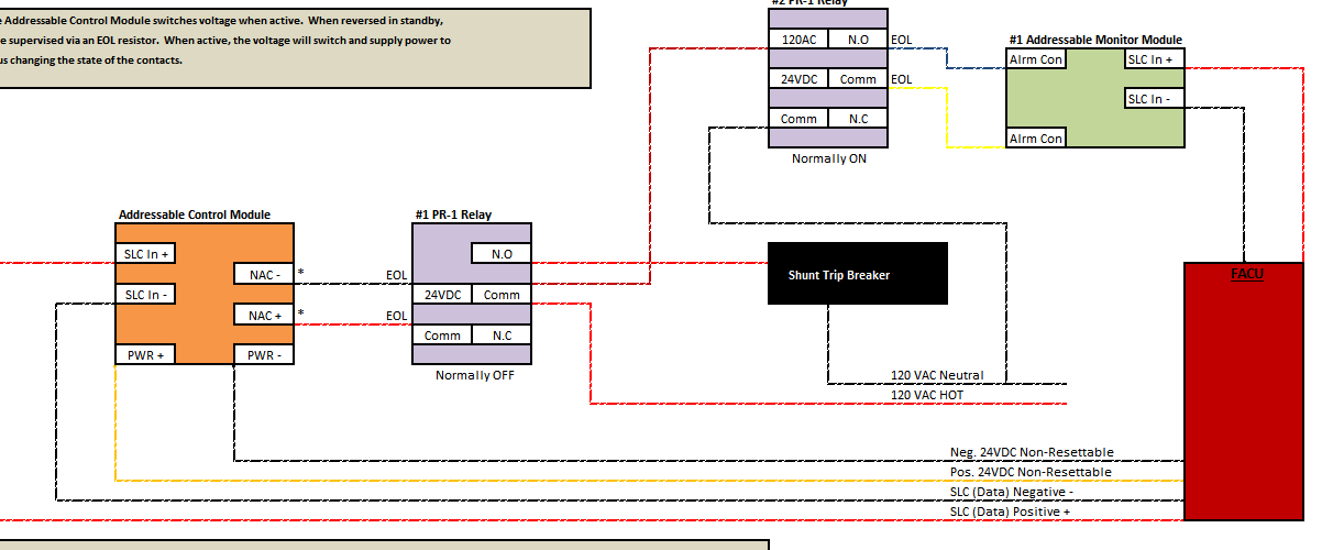
Elevator Shunt Trip Wiring Diagram

The diagram above illustrates a typical concept for interfacing a fire alarm system with an elevator shunt-trip disconnect.

The exact arrangement varies by project. Always use the approved project drawings and equipment-specific wiring diagrams rather than treating a generic diagram as a universal installation detail.

What Is an Elevator Shunt Trip?

An elevator shunt trip is a means of automatically disconnecting electrical power to elevator equipment when required by the elevator/fire protection design.

The objective is not simply to "turn the elevator off."

Where the applicable elevator code requires automatic power shutdown because sprinkler water could create an unsafe elevator condition, the shutdown must occur upon or prior to the application of water.

The fire alarm system commonly interfaces with the electrical disconnect through a control relay or other listed interface equipment.

Elevator Recall and Elevator Shunt Trip Are Different Functions

This distinction is extremely important.

Elevator recall and elevator power shutdown are separate emergency-control functions.

Function Typical Purpose
Elevator Recall Causes the elevator system to respond to a fire alarm recall signal and move according to the approved recall sequence.
Elevator Shunt Trip Disconnects applicable elevator power when automatic power shutdown is required.

A smoke detector used for elevator recall should therefore not be confused with a heat detector used to initiate elevator power shutdown.

Basic Elevator Shunt Trip Sequence

A typical elevator shunt-trip sequence can be understood as:

Heat Detector → Fire Alarm System → Control Relay → Shunt-Trip Disconnect → Elevator Power Removed

The actual system may contain additional monitoring modules, relays, power supplies, disconnects, elevator-controller interfaces, and other components.

Each component serves a specific function and must be coordinated with the approved sequence of operations.

Why Is a Heat Detector Used for Elevator Shunt Trip?

Where automatic elevator power shutdown is required in connection with sprinkler protection, heat detection is commonly used to initiate the shutdown function before sprinkler water is discharged onto elevator equipment.

The purpose is timing.

The shutdown arrangement must coordinate the initiating device and sprinkler so the required power disconnect occurs upon or before water application.

This is different from elevator recall, which is commonly initiated by smoke detection in designated elevator-related locations.

Heat Detector Location Near the Sprinkler

Where heat detection is used to initiate elevator power shutdown, the detector location and temperature characteristics must be coordinated with the sprinkler installation and applicable requirements.

The commonly encountered arrangement places the heat detector within the required proximity of the associated sprinkler so that the detector can respond in time to initiate the shutdown sequence.

Do not simply install one heat detector somewhere in an elevator machine room and assume the requirement has been satisfied. The detector arrangement must correspond with the sprinkler protection and approved design.

Heat Detector Temperature Rating and Sprinkler Temperature

The temperature characteristics of the heat detector and sprinkler are critical.

The goal is for the elevator shutdown sequence to operate before sprinkler discharge when the applicable design requires power removal before water is applied to elevator equipment.

For this reason, the heat detector selection cannot be treated independently from the sprinkler temperature classification and response characteristics.

Design Point: Never select the elevator shunt-trip heat detector solely because a particular temperature rating is normally stocked. Coordinate the detector with the sprinkler and the approved elevator shutdown design.

Fire Alarm Relay for Elevator Shunt Trip

The fire alarm system commonly controls the elevator shunt-trip function through a listed control relay or control module.

When the appropriate heat detector activates, the fire alarm system changes the state of the control output according to the programmed sequence.

That interface then operates the shunt-trip circuit associated with the elevator disconnect.

The exact relay contact configuration, control voltage, wiring method, and fail-safe arrangement depend on the equipment and approved design.

Never assume that normally open or normally closed is universally correct for every shunt-trip installation.

Need the detailed wiring method? For a deeper explanation of ECID placement, supervised control wiring, addressable relay modules, FCM-1 versus FRM-1 operation and external interface relays, see our How to Wire an Elevator Shunt Trip | ECID & Relay Supervision guide.

What Does the Shunt-Trip Breaker or Disconnect Do?

A shunt-trip mechanism allows a circuit breaker or disconnecting means to be electrically operated from a remote signal.

In an elevator power-shutdown application, activation of the required interface causes the applicable elevator power to be disconnected.

The fire alarm control equipment is therefore generally providing the control signal. It is not carrying the elevator motor power through the fire alarm relay.

Critical: Elevator power must never be routed directly through ordinary fire alarm relay contacts unless the equipment is specifically listed and rated for that application. The fire alarm interface normally controls the appropriate listed shunt-trip equipment.

Why Shunt-Trip Control Power Matters

A shunt-trip mechanism needs an available source of control power in order to operate.

That creates an important supervision question:

What happens if the shunt-trip control power is lost before a fire occurs?

If the power necessary to perform the required shutdown is unavailable, the fire alarm system needs to provide the required indication of that impairment where required by the applicable system design and code.

This is why elevator shunt-trip installations commonly include monitoring associated with the availability of the control power.

Monitoring Shunt-Trip Power

A properly designed system should not silently lose the power necessary to perform a required elevator shutdown function.

Depending on the design, the fire alarm system may monitor the availability of the shunt-trip control power through an approved supervisory interface.

If that power becomes unavailable, the fire alarm system can then indicate the abnormal condition rather than leaving a hidden impairment.

The exact monitoring arrangement depends on the disconnect, control-power source, fire alarm equipment, approved plans, and applicable adopted requirements.

What Happens When the Shunt-Trip Heat Detector Activates?

A typical sequence is:

  1. The elevator-area heat detector reaches its operating point.
  2. The fire alarm control unit receives the detector input.
  3. The fire alarm system activates the programmed elevator power-shutdown output.
  4. The associated fire alarm control relay or module changes state.
  5. The shunt-trip mechanism operates.
  6. The applicable elevator power is disconnected.
  7. The fire alarm system provides the required event indications according to the approved sequence.

The actual project sequence may contain additional operations and must always be verified against the approved input/output matrix.

Should Elevator Recall Happen Before Shunt Trip?

Elevator recall and power shutdown are coordinated functions, but technicians should be careful with the common field explanation that the fire alarm system simply "recalls the elevator first and then waits to shunt it."

The power-shutdown function is governed by the required response to the sprinkler hazard and the approved elevator-system design.

Do not create an arbitrary fire alarm timer intended to delay required elevator power shutdown unless that exact arrangement is permitted by the applicable codes, elevator equipment, and approved design.

The fire alarm system should execute the approved sequence rather than improvising a delay in the field.

Smoke Detector vs. Heat Detector for Elevator Functions

Device Common Elevator Function
Smoke Detector Elevator recall and related Phase I emergency operation inputs where required.
Heat Detector Elevator power shutdown where required in coordination with sprinkler protection.
Waterflow Reports sprinkler waterflow but should not automatically be assumed to be the initiating input for the elevator shunt-trip function.

Does Sprinkler Waterflow Shunt Trip the Elevator?

Do not automatically use the sprinkler waterflow switch as the elevator shunt-trip initiating device simply because the shutdown is associated with sprinkler protection.

The purpose of the elevator power-shutdown arrangement is to disconnect the required power upon or prior to the application of water where the elevator code requires that protection.

Waiting for established sprinkler waterflow can be inconsistent with that objective.

Follow the approved heat-detection and shutdown design for the project.

Elevator Machine Room Shunt Trip

Where sprinklers are installed in an elevator machine room, machinery space, control room, control space, hoistway, or other applicable elevator equipment area, the designer must determine whether elevator power shutdown is required by the adopted elevator code and project conditions.

The answer should not be based simply on the fact that the building has elevators or sprinklers.

Modern elevator and sprinkler requirements contain important exceptions and installation options, so each project needs to be evaluated under its adopted codes and elevator design.

Elevator Pit Sprinklers and Shunt Trip

Elevator pits deserve particular attention because the presence of a sprinkler does not automatically mean every pit requires identical fire alarm shutdown equipment.

The sprinkler arrangement, elevator equipment exposure, applicable elevator-code provisions, and approved design determine the required sequence.

Never copy the machine-room shunt-trip design into the pit without verifying the requirements for that specific elevator installation.

NFPA 72 and Elevator Power Shutdown

NFPA 72 addresses the fire alarm system's role in emergency control function interfaces, including elevator-related functions.

The fire alarm system may be responsible for receiving the appropriate initiating-device input, processing the programmed sequence, operating listed control interfaces, supervising applicable pathways or functions, and annunciating abnormal conditions.

However, NFPA 72 is not the only standard involved.

Elevator shunt trip can involve requirements from:

  • NFPA 72, National Fire Alarm and Signaling Code
  • The adopted elevator safety code, commonly based on ASME A17.1/CSA B44
  • NFPA 13 where sprinkler protection is involved
  • NFPA 70 / NEC for electrical installation requirements
  • The adopted building and fire codes
  • Elevator manufacturer requirements
  • Fire alarm equipment listings and instructions
  • The Authority Having Jurisdiction

Do Not Treat the Fire Alarm Diagram as the Complete Elevator Design

A fire alarm drawing may show a heat detector, control module, monitor module, and interface to the elevator disconnect.

That does not necessarily document every part of the elevator electrical installation.

Coordination may be required between:

  • Fire alarm contractor
  • Elevator contractor
  • Electrical contractor
  • Sprinkler contractor
  • Mechanical contractor
  • Engineer of record
  • Fire alarm designer
  • Elevator inspector
  • Fire marshal or other AHJ

Elevator shunt trip is one of those deceptively small details on a fire alarm drawing that can involve several trades.

Testing an Elevator Shunt-Trip Interface

Testing should verify the complete approved sequence rather than merely checking whether a relay LED turns on.

Depending on the project and applicable requirements, coordinated testing should verify items such as:

  • Correct initiating heat detector
  • Correct fire alarm input identification
  • Correct programmed output
  • Operation of the fire alarm control relay or module
  • Operation of the approved elevator power-shutdown interface
  • Required monitoring of control power
  • Correct annunciation at the fire alarm control unit
  • Restoration of the system after testing
  • Coordination with elevator recall and other elevator emergency functions
Testing Warning: Do not intentionally remove elevator power during testing without coordination with the elevator contractor, building representative, and other responsible parties. An uncontrolled shunt-trip test can trap occupants, interrupt building operations, or create equipment and safety problems.

Common Elevator Shunt Trip Wiring Mistakes

  • Confusing recall with shunt trip. They are separate elevator emergency functions.
  • Using the wrong initiating device. Smoke detection and heat detection commonly perform different elevator functions.
  • Using waterflow as the automatic shutdown trigger without verifying the design.
  • Failing to coordinate the heat detector with the sprinkler installation.
  • Ignoring loss of shunt-trip control power.
  • Using an arbitrary software timer to delay shutdown.
  • Assuming every elevator pit or machine room has the same requirements.
  • Using a generic wiring diagram instead of the approved project documents.
  • Failing to coordinate fire alarm, elevator, electrical and sprinkler trades.
  • Testing the fire alarm relay but not the complete integrated function.

Elevator Shunt Trip Quick Reference

Primary Purpose Automatic elevator power shutdown where required
Typical Initiating Device Heat detector associated with applicable sprinkler protection
Fire Alarm Output Listed control relay/module or other approved interface
Controlled Equipment Approved elevator shunt-trip disconnecting means
Separate From Elevator recall
Important Coordination Elevator, fire alarm, sprinkler and electrical systems

Frequently Asked Questions

What is an elevator shunt trip?

An elevator shunt trip is an automatic means of disconnecting applicable elevator electrical power when required by the approved elevator and fire-protection design.

What activates an elevator shunt trip?

Where power shutdown is required in coordination with sprinkler protection, heat detection is commonly used to initiate the fire alarm control sequence that operates the approved shunt-trip interface.

Does a smoke detector shunt trip an elevator?

Smoke detectors are commonly associated with elevator recall functions rather than the sprinkler-related power-shutdown function. The exact operation must follow the approved elevator and fire alarm sequence.

Does a sprinkler waterflow switch shunt trip an elevator?

Waterflow should not automatically be assumed to be the correct initiating input. Where shutdown is required upon or prior to sprinkler water application, the approved design commonly uses heat detection coordinated with the sprinkler rather than waiting for established waterflow.

Is elevator recall the same as elevator shunt trip?

No. Recall commands the elevator system to perform its approved emergency recall operation. Shunt trip disconnects applicable elevator power when power shutdown is required.

Does every elevator require shunt trip?

No. Whether automatic power shutdown is required depends on the elevator equipment, sprinkler protection, adopted elevator code, building conditions, and approved design.

Does every sprinkler in an elevator area require a heat detector?

Not automatically. The required detection and shutdown arrangement depends on whether automatic elevator power shutdown is required for that sprinkler/elevator condition under the applicable codes and approved design.

Why is shunt-trip power monitored?

If electrical power necessary to operate a required shunt-trip function is lost, the shutdown function can become impaired. Where required, monitoring allows that abnormal condition to be reported rather than remaining hidden.

Can the fire alarm relay directly switch elevator motor power?

Ordinary fire alarm control contacts are generally used to interface with the approved elevator power-shutdown equipment, not to carry elevator motor power. Always follow the equipment listings and approved electrical design.

Related Elevator Fire Alarm Guides

Final Thoughts

The key to understanding elevator shunt-trip wiring is recognizing that the fire alarm system is only one part of an integrated elevator power-shutdown function.

The heat detector provides the initiating condition. The fire alarm system processes that condition and operates the approved control interface. The shunt-trip equipment disconnects the required elevator power.

Meanwhile, elevator recall remains a separate emergency function with its own initiating devices and sequence.

For a successful installation, the fire alarm, elevator, sprinkler and electrical designs all have to agree on the same sequence of operation.

Technical Disclaimer: This article is intended for educational use by qualified fire alarm and life-safety professionals. Elevator power shutdown is an integrated life-safety function. Always follow the adopted codes and standards, approved construction documents, elevator manufacturer requirements, equipment listings, electrical-safety procedures, and AHJ requirements for the specific installation.

Saturday, December 17, 2016

How to Wire an Elevator Shunt Trip | ECID & Relay Supervision

Proper elevator shunt trip wiring involves more than simply connecting a fire alarm relay to a shunt-trip breaker. The fire alarm designer must identify the emergency control interface device (ECID), determine which control pathway requires supervision, verify the electrical characteristics of the controlled circuit, and select an interface device suitable for the application.

This guide focuses specifically on the fire alarm interface and supervision side of elevator shunt-trip wiring, including ECID placement, addressable modules, interface relays and control-circuit supervision.

If you are looking for the complete elevator shutdown sequence instead, including the heat detector, fire alarm relay, shunt-trip disconnect, sprinkler relationship and elevator power removal, see our Elevator Shunt Trip Wiring Diagram & Power Shutdown Guide.

Important: The wiring arrangements shown here are educational examples. Elevator power shutdown is an integrated life-safety function. Always follow the adopted codes, approved drawings, fire alarm and elevator equipment instructions, electrical requirements, equipment listings and the AHJ-approved sequence of operations.

Elevator Shunt Trip Wiring Diagram

The diagram above illustrates two concepts for interfacing a fire alarm system with elevator shunt-trip equipment.

The important concept is not the specific NOTIFIER part number. It is understanding where the emergency control interface occurs and how the fire alarm control pathway is supervised.

What Is an ECID?

ECID stands for Emergency Control Interface Device.

In practical fire alarm design, the ECID is the interface through which the fire alarm system performs the required emergency control function.

For an elevator power-shutdown application, the ECID may be an addressable fire alarm interface located appropriately for the controlled equipment, or the design may use a supervised fire alarm control circuit operating another listed interface relay.

Which device serves as the actual interface depends on the system architecture.

This distinction matters because moving the interface farther away from the addressable fire alarm module can create an additional field-wiring pathway that must be considered in the supervision design.

The Basic ECID Concept

A useful way to visualize the arrangement is:

FACU → Supervised Fire Alarm Pathway → ECID → Controlled Emergency Function

For an addressable fire alarm system, the signaling line circuit itself is supervised by the fire alarm control unit.

However, simply having an addressable module somewhere in the system does not automatically mean every conductor beyond that module is supervised.

That is the key issue this article addresses.

Method 1: Addressable Relay at the Elevator Interface

One approach is to locate an addressable relay module at the point where the fire alarm system interfaces with the elevator power-shutdown control equipment.

The original example used a NOTIFIER FRM-1 addressable relay module.

The FRM-1 communicates with the compatible fire alarm control panel over the SLC and provides isolated Form-C relay contacts for controlling external equipment.

Conceptually:

FACU → Supervised SLC → Addressable Relay at Interface → Shunt-Trip Control Equipment

Locating the addressable interface at the controlled equipment can minimize the amount of unsupervised control wiring between the fire alarm interface and the equipment being controlled.

Important distinction: The FRM-1's addressable SLC connection is supervised by the fire alarm system, but its dry relay contacts do not magically supervise whatever external circuit is connected to those contacts. The complete interface must still be evaluated according to the approved design and applicable supervision requirements.

NOTIFIER FRM-1 Relay Module

The FRM-1 is an addressable relay module that allows a compatible NOTIFIER fire alarm control panel to operate dry relay contacts by command.

It provides two isolated Form-C contact sets that operate together.

This makes the FRM-1 useful for many fire alarm emergency-control interfaces where dry contacts are appropriate.

But there is an important limitation:

The FRM-1 is a relay module, not a universal power-control device.

The circuit being switched must remain within the manufacturer's listed contact ratings for the specific:

  • Voltage
  • Current
  • AC or DC application
  • Resistive or inductive load
  • Coded or non-coded operation where applicable

Never choose an interface relay based solely on its largest advertised ampere rating.

Why Relay Contact Ratings Matter

Relay contacts are not rated identically for every electrical load.

A contact capable of switching one current at a low-voltage resistive load may have a significantly different rating when switching an inductive load or a different voltage.

Shunt-trip coils and other control equipment can present electrical characteristics that must be checked against the relay manufacturer's published ratings.

Do not assume: A relay marked for a particular maximum current is automatically suitable for every shunt-trip circuit below that current. Verify the actual voltage, current and load type against the manufacturer's listed contact ratings.

What If the Fire Alarm Relay Cannot Directly Control the Load?

If the fire alarm relay contacts are not suitable for the circuit being controlled, the design can use an appropriately rated listed interface relay.

The fire alarm system then controls the interface relay rather than attempting to switch the external control load directly.

Conceptually:

FACU → Supervised Control Module → Interface Relay → Shunt-Trip Control Equipment

This is where the supervision design becomes especially important.

Method 2: FCM-1 With an External Interface Relay

The second arrangement in the original diagram uses a NOTIFIER FCM-1 addressable control module to operate an external interface relay.

This is fundamentally different from using an FRM-1.

The FRM-1 provides addressable dry relay contacts.

The FCM-1 provides a supervised control output designed to monitor the wiring connected to its output circuit.

NOTIFIER documentation describes the FCM-1 as capable of supervising its output wiring and reporting conditions such as normal, open and short to the fire alarm control system.

That capability is why a supervised control-module arrangement can be useful when an external interface relay must be located away from the addressable module.

Why Use an External Interface Relay?

An external interface relay may be necessary when:

  • The controlled voltage exceeds the appropriate rating of the fire alarm relay contacts
  • The controlled current exceeds the appropriate contact rating
  • The load characteristics are not suitable for the addressable relay
  • The project design requires a different listed interface
  • A supervised control circuit must extend from the fire alarm module to the final interface

The interface relay must itself be properly selected for the electrical characteristics of the controlled circuit.

The original diagram used a PR-1 style interface relay as an example. The exact relay used on a modern project should be selected from the approved equipment for that particular system rather than treating one legacy part number as universally required.

FRM-1 vs. FCM-1 for Elevator Shunt Trip

Feature FRM-1 FCM-1
Basic Device Type Addressable relay module Addressable control module
Typical Output Dry Form-C relay contacts Supervised control output
Output Wiring Supervision Dry contacts do not inherently supervise the external controlled circuit Designed to supervise connected control wiring when installed as specified
Useful Application Local dry-contact interface where appropriate Supervised pathway to an external interface/load where appropriate
Key Design Check Contact voltage/current/load rating Compatible external supply, supervised circuit and connected load

Why Module Location Matters

One of the easiest mistakes to make with emergency-control wiring is to focus entirely on the fire alarm panel and ignore where the actual interface device is located.

Consider two arrangements:

Arrangement A:

FACU → SLC → Addressable Interface → Controlled Equipment

Arrangement B:

FACU → SLC → Addressable Module → Long Field Control Circuit → Interface Relay → Controlled Equipment

Arrangement B introduces another pathway between the addressable module and the final interface.

That pathway cannot simply be ignored because the module itself has an address.

If the design requires supervision of that control pathway, the module and circuit architecture must provide that supervision.

What Wiring Is Actually Supervised?

This is the question every technician should ask when looking at an elevator shunt-trip interface.

Do not stop at:

"The module is addressable, so it's supervised."

Instead ask:

  • Is the SLC supervised?
  • Where is the emergency-control interface located?
  • Is there additional wiring between the addressable module and that interface?
  • Is that additional wiring supervised where required?
  • Is external control power monitored where required?
  • Would an open conductor prevent the required emergency function without creating a trouble indication?

Those questions expose the difference between an addressable device and a completely supervised emergency-control interface.

Supervising Shunt-Trip Operating Power

The control pathway is only part of the design.

The shunt-trip mechanism also needs the electrical power necessary to perform its required function.

If that operating power disappears, the fire alarm control relay could function perfectly while the elevator power-shutdown mechanism fails to operate.

Where required by the applicable design and code, loss of power necessary for the emergency control function must therefore be monitored so the impairment does not remain hidden.

The exact method depends on the shunt-trip equipment, control-power source and approved fire alarm design.

Do Not Confuse Control Power With Elevator Motor Power

The fire alarm system normally interfaces with the control side of the elevator power-shutdown equipment.

It is not routing the elevator motor feeder through an ordinary addressable fire alarm module.

The fire alarm interface operates the approved shunt-trip or disconnecting mechanism, which then performs the required power-disconnection function.

This distinction is important both electrically and from an equipment-listing standpoint.

Normally Open or Normally Closed?

There is no responsible universal answer that says every elevator shunt-trip interface should simply use the normally open or normally closed contacts of a relay.

The correct contact arrangement depends on:

  • The shunt-trip equipment
  • The control voltage
  • The approved sequence
  • The supervision method
  • The interface relay
  • The required normal and activated states
  • The equipment manufacturer's instructions

Follow the approved wiring diagram rather than selecting NO or NC based on habit.

Do Not Use the SLC as Proof That Everything Is Supervised

This deserves repeating because it is a common misunderstanding.

An addressable module being supervised on the SLC proves that the fire alarm control unit can communicate with that module.

It does not automatically prove that every conductor, relay coil, external power supply, or controlled circuit beyond the module is supervised.

Each part of the emergency-control interface must be evaluated according to what happens if that portion of the circuit opens, shorts, loses power or otherwise becomes impaired.

Common Elevator Shunt Trip Interface Mistakes

  • Using a relay without checking its actual contact rating.
  • Assuming an addressable relay supervises wiring connected to its dry contacts.
  • Installing the addressable module far from the final interface without evaluating the intervening wiring.
  • Confusing an FRM-1 relay module with an FCM-1 supervised control module.
  • Failing to monitor power required to perform the shutdown function where required.
  • Routing loads through fire alarm contacts that are not listed or rated for the application.
  • Assuming NO or NC contacts are universally correct.
  • Using legacy part numbers without checking current product documentation and compatibility.
  • Testing only the fire alarm module rather than the complete emergency-control function.

Testing the Elevator Shunt Trip Interface

Testing should verify more than whether the addressable module changes state.

The complete test should be coordinated with the elevator contractor and other responsible parties and should verify the approved sequence from initiating condition through the final controlled function.

Depending on the installation, this can include:

  • Correct fire alarm input
  • Correct system programming
  • Addressable module operation
  • Supervision of the applicable control pathway
  • External interface relay operation
  • Availability and monitoring of required control power
  • Operation of the approved elevator shutdown interface
  • Correct trouble indication when a supervised pathway is intentionally opened during testing
  • Proper restoration after the test
Testing Warning: Never intentionally interrupt elevator power simply to prove a fire alarm output without proper coordination. Elevator shutdown testing should be performed as an integrated test with the appropriate elevator, electrical, fire alarm and building personnel involved.

Frequently Asked Questions

What is an ECID in a fire alarm system?

ECID stands for Emergency Control Interface Device. It is the interface through which the fire alarm system performs an emergency control function such as an approved elevator power-shutdown operation.

Can an FRM-1 be used for elevator shunt trip?

An FRM-1 provides addressable dry relay contacts and may be suitable for an approved emergency-control interface when its application, contact ratings, location, supervision arrangement and equipment compatibility satisfy the project requirements. It should not be treated as a universal shunt-trip solution.

What is the difference between an FRM-1 and FCM-1?

The FRM-1 is primarily an addressable relay module providing Form-C dry contacts. The FCM-1 is an addressable control module capable of supervising its connected output wiring when installed in accordance with the manufacturer's instructions.

Does an addressable relay automatically supervise the shunt-trip circuit?

No. The fire alarm system supervises communication with the addressable module, but dry relay contacts do not automatically supervise all external wiring connected beyond those contacts.

Why would I use an FCM-1 with an interface relay?

A supervised control module can be useful where the fire alarm system must supervise the control wiring extending to an external interface relay. The external relay can then be selected for the electrical characteristics of the controlled circuit.

Can I use any 10-amp relay for elevator shunt trip?

No. Relay suitability depends on more than a single ampere rating. Verify voltage, AC or DC operation, load type, contact rating, listing, control characteristics and compatibility with the approved design.

Does the fire alarm relay carry elevator motor power?

Normally, no. The fire alarm system interfaces with the control circuitry for the approved elevator power-disconnection equipment. Elevator motor power is not normally routed through an ordinary addressable fire alarm relay.

Related Elevator Fire Alarm Guides

Final Thoughts

The most important concept in elevator shunt-trip interface wiring is understanding exactly where the emergency control interface occurs.

If an addressable relay is located at the final interface, the supervised SLC brings the fire alarm system directly to that point, but the dry contacts themselves do not automatically supervise the external circuit.

If an external interface relay must be located beyond the addressable device, a supervised control-module arrangement may be appropriate so the wiring to that interface can be monitored.

In either case, the designer must verify the relay ratings, control voltage, supervision requirements, equipment listings and approved elevator shutdown sequence.

Don't ask only, "Is the module supervised?" Ask, "Is the entire required control pathway supervised to the point where the emergency function is actually performed?"

Technical Disclaimer: This article is intended for qualified fire alarm and life-safety professionals. Always follow the currently adopted codes and standards, approved construction documents, equipment listings, manufacturer instructions, electrical-safety requirements and AHJ requirements for the specific installation.