Showing posts with label system sensor. Show all posts

Monday, April 22, 2019

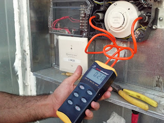
Using a Manometer to Test Duct Smoke Detectors

A Manometer is an electronic device commonly referred to as a liquid column hydro-static instrument.  A Manometer measures pressure and vacuum between the actual duct smoke detector's sample tubes. These manometer units can be used with other manufacturer's duct detectors but for this example we will stick with the System Sensor DNR. 

Manometer Testing Duct Smoke DetectorThe Manometer we chose to use for this article is the Duct Checker manufactured by SDI.  The Duct Checker is light weight, portable and battery operated making it easy to get to areas duct smoke detectors are commonly found. Simply connect the two provided hoses with variable size end plugs and power it on.  Once the unit turns on, press down the "hold" button for three seconds to zero out the machine.  Sort of like a scale.  Now press the "unit" button until you arrive at the selection of "inH2O" on the bottom left of the screen.

The Duct Checker comes with two hoses that are designated for specific ports.  One tube is marked as negative and the other positive.  Make sure to place the hose end of the positive into the actual sample tube inlet.  The negative tube will go into the exhaust port. 

With the System Sensor DNR duct detector you will be looking for a reading of anywhere between 0.01 min and 1.11 max.

Duct Checker Manometer from SDi


With this requirement clearly required in NFPA 72 2016 Table 14.4.3.2 section 17 (g)(5), as well as most manufacturer's documentation, you can expect to come across these at some point in your career.  They are not too pricey so I suggest grabbing one from SDi and placing them in your inspection crew's service vehicles.

Thursday, March 12, 2015

System Sensor D4120 Tamper Troubles

System Sensor D4120 InnovairFlex Duct Smoke Detectors 

These conventional duct smoke detectors include a tamper switch feature that results in a trouble signal at the fire control panel when the duct detector cover has been removed or is not properly installed. If your System Sensor D4120 duct smoke detector is displaying a solid Amber LED, then this is the device's indication that the cover is either missing or not properly tightened down. Keep in mind that this trouble condition will also disable the System Sensor's detector test feature, which is activated using one of the following methods; the Push Button on the power board, the Magnet Test or Remote Test Stations.

System Sensor D4120 Duct Smoke Detector

If you are experiencing this trouble condition, ensure that the System Sensor D4120 duct detector cover of the device is properly aligned and the connecting screws are tightened firmly. When properly attached, a small pole on the cover should contact the bottom left terminal of the tamper switch and depress to contact a terminal on the underside of the cover, closing the tamper switch.

Tuesday, October 1, 2013

System Sensor D4120 Duct Detectors Connected the Right Way

If you are involved in the fire alarm industry then chances are you have come across conventional 4-wire duct smoke detectors. Now with new technology, addressable versions of these duct detectors have made connections, wire pulling and programming a lot easier.  Not to mention the cost savings.  In this article, I want to cover the proper method for connecting multiple 4-wire conventional duct smoke detectors on one single IDC (Initiating Device Circuit).  This could be a connection directly off of a conventional loop card or even an addressable monitor module.
Fire Alarm Duct Detector

For reference, we are going to be covering the connections on the System Sensor D4120 model duct detector as this is the most common version used by mechanical contractors.  Also note that the System Sensor D4120 is the replacement for the DH100ACDCLP.  The reason to mentioned this is the fact that System Sensor was smart when creating the newer D4120 by carrying over the same terminal numbers for the connections on the board.  If you were used to connecting to the DH100ACDCLP then you know the alarm contacts were on terminals #4 and #5. Well even though the terminals on the D4120 are not in the same location, they have the same numbers.

When connecting one conventional duct smoke detector, we know that we have to wire the EOL (end of line) resistor in series through the supervisory contacts #3 and #14.  This is a method that is absolutely necessary as it is the only way to properly supervise the detector and IDC.  If the duct detector losses power, has the cover opened, dirty sensor, or a internal wiring problem between the board and the sensor, the supervisory contacts will open thus creating an open circuit and a trouble at the FACP.

Now if we have multiple duct smoke detectors on a single IDC loop, then we need to make sure we wire the EOL resistor in series through all of the detectors on the loop.  This means running an additional pair of wires during the rough in stage.  One pair of wires will be for the IDC (alarm contacts #4 and #5), the second pair will be for the EOL and supervisory contacts (#3 and #4) and the last pair will be for the 24 volts DC resettable power.  Please note that one of the wires on the supervisory pair will run all the way from the last duct detector (terminal #5) on the loop to the first (terminal #14), while the second wire of the pair connects the supervisory contacts of each detector (#3 to #14) on the loop.


If you were to wire the IDC pair through all of the alarm contacts and place the EOL resistor in series through the supervisory contacts on the last duct detector only what would happen?  The answer is, each duct detector would go into alarm, however only the wiring/circuit would be monitored for integrity.  If you do not wire the resistor through each of the detectors supervisory contacts, you are not monitoring the status of the detector itself.  An example would be:  you have three System Sensor D4120 duct detectors on a single loop.  Coming off of your addressable monitor module, you are landing on the alarm contacts of all three detectors.  When you get to the third detector you wire the EOL resistor in series through the supervisory contacts.  Technically the third device is the only detector on the loop that is properly supervised.  If the first duct detector had a loose cover and the second had lost power, you would never know as long as the third device was working properly.  You and the FACP would only know of a trouble on the first two detectors if the third detector had a fault.  This is why it is so important to follow this method.

Key Note***** Make sure to always meter out the supervisory contacts as different duct smoke detector manufacturers label them differently.  Sometimes the contacts reverse when powered up.  In the case of the System Sensor D4120, the resistor is wired through the Common and Normally Open contacts.  Once the unit is powered up and free of any faults, the contacts will reverse and close up and complete the circuit. 

Keep in mind that this method is also required when wiring any other fire alarm device that has separate supervisory or trouble contacts.  The big one to mention is beam detectors.

Make sure to join our Facebook Group HERE
Wednesday, June 19, 2013

Drywall Dust Problems with System Sensor Smoke Detector

If any packaged air conditioning units are run during the drywall installation phase of building construction to assist in the drying of joint compound, the fine dust created by sanding of those drywall joints may compromise the System Sensor smoke detector sensor heads within the duct housing. The 2D51 System Sensor Head in the InnovairFlex Duct Smoke Detector models D4120, D4120W and D4S may display a “maintenance” condition that will require replacement or cleaning of the sensing chambers on the smoke detector head. The “maintenance” condition will be indicated on the fire alarm control panel, on the sensor itself or power board of the duct smoke detector (the sensor LED will blink “red” every five seconds and the power board LED will blink “amber” every five seconds).

To avoid this condition, it is recommended that the System Sensor smoke detector heads be removed during the construction phase and replaced once construction is completed and the Certificate of Occupancy is issued. The sensor heads twist out for removal and twist in for insertion.

Below is an extracted image of the System Sensor duct smoke detector sensor head:


Cleaning the sensing chamber on the sensor head

If the System Sensor smoke detector heads are not removed during the construction phase and the sensor chamber becomes dirty causing a maintenance condition (it will not always be visible on the exterior black screen on the sensor head), the sensor head must be cleaned with compressed air. To clean the sensor head chamber, follow these step-by-step instructions see the video demonstration below:

1. Remove the System Sensor smoke detector head to be cleaned from the duct smoke detector housing by twisting it in a counterclockwise direction.
2. Remove the smoke sensor cover by pulling outward on each of the four removal tabs that hold the cover in place.
3. Vacuum the screen carefully without removing it. If further cleaning is required continue with Step 4. Otherwise, skip to Step 7.
4. Remove the chamber cover/screen assembly by pulling it straight out.
5. Use a vacuum cleaner or compressed air to remove dust and debris from the sensing chamber.
6. Reinstall the chamber cover/screen assembly by sliding the edge over the sensing chamber. Turn until it is firmly in place.
7. Replace the cover using the holes for the LEDs for alignment and then gently push it until it locks into place.
8. Reinstall the System Sensor smoke detector head in the duct smoke detector housing by aligning it in the housing and twisting it in a clockwise direction.

Note: Cleaning only the sensor head’s exterior black screen will not remove any drywall dust in the smoke sensing chamber.
Note: Should the System Sensor duct smoke detector remain in a “maintenance” condition after cleaning, then it may require the complete replacement of the sensor head. The replacement sensor head is model 2D51.


SLC Circuit for Duct Detectors Done the Easy Way

Okay we are back to the amazing installation practices that some fire alarm and security companies will perform to lower their labor time and land the job. However, after you will see in this amazing video you will wonder how some of these companies get away with it. And if they are doing these installs after the acceptance test, then how are they living with themselves? Better yet, how does the customer not make themselves aware of what they are paying for? Words cannot express the frustration that myself and other competent contractors feel when they see installs like this.

Here is what we have for you today. This video shows a quick clip of some conventional System Sensor duct smoke detectors installed within the rooftop HVAC unit. However, the previous fire alarm contractor thought it would be a good idea to run a standard 18 awg (American wire gauge) 2 conductor PVC cable open wire across the rooftop from unit to unit. They drilled a hole in the side of each HVAC roof top unit and proceeded to run this PVC cable across the roof and tied them directly to the addressable module for each System Sensor duct smoke detector. This was obviously done because the contractor was one of two things: 1 he was to lazy to get a scissor lift below the deck and find the problem, or 2 he was just not competent enough to resolve the issue without pulling off this nightmare. You be the judge!


Sunday, May 19, 2013

Wow System Sensor D4120 Duct Detector is Now Fixed

System Sensor D4120 DNR Duct Smoke DetectorA while back I posted on the new System Sensor D4120 duct smoke detector. I stated that although a great improvement on the previous DH100 series it did have one major flaw. The System Sensor D4120 duct smoke detector would open the supervisory contact when powered up causing a trouble condition at the main fire control panel every time the end user or tech performed a reset. This was a major deal especially when you have a new high rise with over 60 of these new System Sensor D4120 duct detectors. The AHJ (authority having jurisdiction) typically does not understand why the fire control panel starts receiving 60 troubles when you reset the system.
Our tech department has been contacting System Sensor for months (ever since this device came out) trying to get an answer as to why they did this.

Well I am happy to report that System Sensor finally listened and has corrected the issue. Now when power is restored to the D4120 the supervisory contact will close immediately. Great job System Sensor with what we can now call another awesome product.

Read more from System Sensor here.