Showing posts with label elevator equipment. Show all posts

Friday, August 25, 2017

Occupant Evacuation Elevator Code Explained

What is an Occupant Evacuation Elevator?


Much like Fire Service Access Elevators, Occupant Evacuation Elevators are in fact elevators that have strict rules and regulations put in place to allow special uses above standard elevators.  An Occupant Evacuation Elevator can be used for self-evacuation during a fire emergency pending the elevator system meets the requirements set forth in the International Building Code.

Occupants Running to the Elevator During Fire


What Code Requires or Allows the Use of Occupant Evacuation Elevators?


The requirement to provide occupant evacuation elevators can be found in the IBC or International Building Code 2021 section 403.5.2 within the EXCEPTION.

"For buildings other than Group R-2 that are more than 420 feet in building height, one additional interior stairway meeting the requirements of Sections 1011 and 1023 shall be provided in addition to the minimum number of exits required by Section 1006.3.  The total width of any combination of remaining interior exit stairways with one interior exist stairway removed shall be not less than the total width required by Section 1005.1.  Scissor stairways shall not be considered the additional interior exit stairway required by this section."

Exception: An additional interior exit stairway shall NOT be required to be installed in buildings having elevators used for occupant self-evacuation in accordance with Section 3008."

Furthermore, the International Building Code 2021 Section 403.6.2 Occupant Evacuation Elevators.  States, "Where installed in accordance with Section 3008, passenger elevators for public use shall be permitted to be used for occupant self-evacuation."

The requirements on how an occupant evacuation elevator is to be installed can be found in the IBC or International Building Code 2021 section 3008.

Other references include:

Requirements for Occupant Evacuation Elevators


When an occupant evacuation elevator is to be used for occupant self-evacuation during a fire, all passenger elevators for public use shall comply with Sections 3008.1 through 3008.10.  If any additional elevators are are used for self-evacuation, those elevators shall comply with these sections as well.

In buildings that utilize occupant evacuation elevators, a fire safety and evacuation plan shall be approved and in place.  Requirements for a fire safety and evacuation plan can be found in the International Fire Code (IFC) 2021 section 404 "Emergency Planning and Preparedness".

The operation of self-evacuating occupant evacuation elevators shall comply with the requirements in ASME A17.1, CSA B44 and the above mentioned Fire Safety and Evacuation Plan.

Emergency Voice Communication System


The building shall be equipped with an emergency voice/alarm communication system that is accessible to the fire department.  System shall be installed in accordance to section 907.5.2.2.  Each elevator lobby used for occupant evacuation shall be equipped with at least one audible and one visual notification appliance.  Not that it would be common but if you had to install voice evacuation just for the occupant evacuation elevators, it is allowed to mix audible evacuation tones.  Find out more in this article, "Mixing Speakers and Horns for Fire Alarm."

Automatic Sprinkler Requirements:


The building with occupant evacuation elevators shall be protected throughout with an approved automatic sprinkler system in accordance with section 903.3.1.1.  The automatic sprinkler system shall be provided with a supervised tamper switch and alarm initiating water flow switch on every floor of the building.  Note, the following areas are prohibited from having automatic fire sprinkler protection:

  • Elevator Machine Rooms  
  • Elevator Machinery Spaces
  • Elevator Control Rooms
  • Elevator Control Spaces
  • Elevator Hoistways serving the Occupant Evacuation Elevator

The lobby on each floor served by the fire service access elevator shall have an approved method of preventing water from the operation of the automatic sprinkler system from infiltrating the FSAE hoistway.

Lastly, a means for elevator shutdown or Shunt Trip in accordance with IBC section 3005.5 shall NOT be installed on elevator controllers used for occupant evacuation elevators.

Occupant Evacuation Elevator Hoistway Enclosure


The shaft or hoistway enclosure shall comply with IBC section 713 "Shaft Enclosures" as well as section 403.2.3.4 "Wall Assembly" and sections 403.2.3.4 "Other Wall Assemblies".

Occupant Evacuation Elevator Cab Dimensions


Although this is not a direct requirement for occupant evacuation elevators or fire service access elevators rather buildings that are four stories or more, it still applies and is worth mentioning.  IBC section 3002.4 "Elevator Car to Accommodate Ambulance Stretcher" gives us the dimensions required for the cab.  "The elevator car shall be of such a size and arrangement to accommodate an ambulance stretcher 24 inches by 84 inches with not less than 5 inch radius corners, in the horizontal, open position.  ADA Table 407.4.1 breaks this down a little further and gives us the following:  The cab shall be provided with a minimum clear distance between walls and door excluding return panels not less than 80 inches by 54 inches and a minimum distance from wall to return panel not less than 51 inches with a 42 inch side slide door.

Fire Service Access Elevator Car Dimensions
Fire Service Access Elevator and Occupant Evacuation Elevator Car Dimensions

Stretcher inside FASE Elevator Cab


Occupant Evacuation Elevator Lobby Requirements

The Occupant Evacuation Elevator lobby shall be enclosed with a smoke barrier having a fire-resistance rating of not less than 1 hour.  The occupant evacuation elevator lobby doorways shall comply with Section 3008.6.3.  NOTE: Just like Fire Service Access Elevators, enclosed occupant evacuation elevator lobbies are NOT required at the levels of exit discharge

Lobby Sizing

Keep in mind the following for occupant evacuation elevator lobby sizing requirements:

  1. The occupant evacuation elevator lobby shall accommodate 3 square feet per person, not less than 25 percent of the occupant load of the floor area served by the lobby.
  2. Occupant evacuation elevator lobbies shall be able to house one wheelchair with a space of 30 inches by 48 inches for every 50 persons within the area the lobby serves.
There is an exception to these 2 rules.  The size of an elevator lobby that serves multiple banks of elevators shall have the minimum area APPROVED on an individual basis.  This sizing shall be consistent with the building's fire safety and evacuation plan.

Lobby Doors

The occupant evacuation elevator lobby doors shall be provided with a 3/4 hour fire door assembly complying with Section 716.5.  Doors shall comply with the smoke and draft control assembly requirements of Section 716.5.3.1 and UL 1784 test conducted WITHOUT the artificial bottom seal.

There shall also be a fire protection rated glazed vision window within the occupant evacuation elevator lobby doors.

No different from standard elevators or fire service access elevators, the lobby doors of occupant evacuation elevator lobbies shall close upon receipt of the fire alarm system serving the building.

The self closing mechanism shall close the door from a fully open position (90 degrees) to 12 degrees from the latch at a minimum of 5 seconds.  This insures the doors do not close to quickly.  This information can be located in ANSI 117.1 2009 section 404.2.7.1.

How are Occupant Evacuation Elevators Designated or Noticed?


On all floor served by the occupant evacuation elevator, there shall be an approved sign posted adjacent to each call station.  We suggest consulting with your local AHJ if they have a standard on this signage.  

Occupant Evacuation Elevator System Monitoring


The occupant evacuation elevator shall be continuously monitored at the fire command center (FCC) or a central control point approved by the AHJ.  The following information shall be displayed or available:

  1. The location of each elevator car
  2. The travel direction of each elevator car
  3. If the elevator car is occupied or not
  4. Status of normal power conditions to the elevator equipment, machinery, electrical apparatus cooling equipment, elevator machine room, control room and control space ventilation and cooling equipment.
  5. Status of standby or emergency power conditions to the elevator equipment, machinery, electrical apparatus cooling equipment, elevator machine room, control room and control space ventilation and cooling equipment.
  6. Activation of any fire alarm initiating device in any elevator lobby, elevator machine room, machine space containing a motor controller or electric driving machine, control space, control room or elevator hoistway.


Elevator Landing Two-Way Communication System


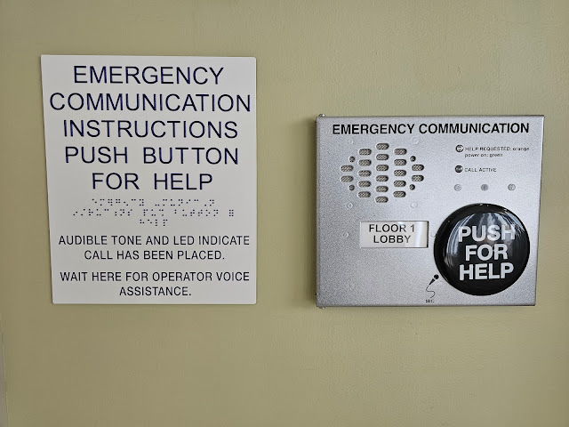
You are required to provide a two-way communication system at the lobby of each level served by an occupant evacuation elevator.  The two-way communication call stations shall initiate communication to the building's fire command center or an alternate location approved by the AHJ.  Note the two-way communication system shall be installed in accordance with sections 1009.8.1 and 1009.8.2

SPACE AGE ELECTRONICS SHIELD 30 TWO-WAY COMMUNICATION SYSTEM

      
Space-Age-Shield-30-Two-Way-Communication


Electrical Power


The following features serving each occupant evacuation elevator shall be provided with both normal power as well as Type 60/Class 2/Level 1 standby power:
  1. Elevator equipment
  2. Elevator hoistway lighting
  3. Ventilation for elevator machine rooms, elevator control rooms, machine and control spaces.
  4. Elevator cab lighting
He is the big one to watch out for.

Protection of Wiring and Cables for Occupant Evacuation Elevators


Wires and cables located OUTSIDE of the fire service access elevator lobby and machine room that are provided for the fire-detection system shall be protected by construction having a fire-resistance rating of not less than 2 hours, shall be circuit integrity (CI) cable with a rating of not less than 2 hours or shall be protected by a listed electrical protective system having a rating of not less than 2 hours.

2-Hour CI Cable for Fire Alarm

Hazardous Material


The building shall not contain any hazardous material areas exceeding the maximum allowable quantities per control area as noted in section 414.2


All code references for this article are found in the 2021 Edition of the International Building Code.

Monday, August 7, 2017

Temperature Sensors for Fire Service Access Elevators

Code Background for Fire Service Access Elevators


In a previous post, we discussed the importance of Fire Service Access Elevators or FSAE based on their ability to assist first responders in the evacuation of occupants in the event of a fire.  These fire service access elevators are becoming more and more advanced with special requirements to insure the safety of operators during a high rise structure fire.  Most of the requirements outlined in the previous post "Fire Service Access Elevators Explained",  are found in the International Building Code or IBC.  The FSAE sections include 403.6.1 and 3007.1 - 3007.9.  However, in the State of California we go by the California Building Code or CBC.  The only major difference spelled out in the CBC is the section on Fire Service Access Elevator "Phase 1 Recall".  In the CBC the requirements for the Phase 1 Recall are as follows:  "Activation of ANY initiating device within the building shall active the phase 1 recall of all fire service access elevators.  All standard elevators shall remain in the normal operation unless they are manually taken over via key or the activation of their associated fire alarm initiating devices."

Now as with most jurisdictions and AHJs, you will more than likely have to deal with local adopted ordinances.  These are alterations to the adopted code by your AHJ.  Once these ordinances have become officially adopted, they override the National or State Code.  A perfect example of this is San Francisco's "Administrative Bulletin #5.08"  better known as AB #5.08.  San Francisco Fire Department (SFFD) has adopted this bulletin making it the new code.

Where is the Requirement for Temperature Sensors in FSAE Lobbies?


In the SFFD AB #5.08 titled "Fire Service Access Elevators" section 3.0 (e) you will find the following language:

"An approved means for firefighters to monitor heat conditions in FSAE lobbies and associated machine/control rooms, such as analog heat sensing system annunciated at the Fire Command Center (FCC). This is intended to provide firefighters with more information to determine whether the FSAE protection has been compromised. This means shall include a dedicated FSAE Status Panel located at the FCC. (Reference NFPA 72-2019 Section 21.5 indicated in item 4.g below)"

This requirement is in place to give the first responders a live reading of the temperature present in a given fire service access elevator lobby before traveling to the area.  This requirement makes the standard code found in the IBC section 3007 a little more complicated and costly however the benefits of life safety are worth it.

Now the code above does not exactly tell us how to display this requirement other than using an Approved Means.  Currently in San Francisco, we are using a custom LED annunciator with individual LEDs depicting 3 different temperature ranges and 1 LED for fault per FSAE lobby.  The temperature ranges are as follows:

  • NORMAL < or = 90 degrees (GREEN LED)
  • MONITORING 90 to 135 degrees (AMBER/YELLOW LED)
  • UNSAFE > 135 degrees (RED LED)
FSAE Fire Service Access Elevator Temperature LEDs
Fire Service Access Elevator Temperature LEDs


You can see a screenshot of a Fire Service Access Elevator dedicated status panel in our previous article title "Fire Service Access Elevators Explained".

How do We Monitor Heat Conditions Within the FSAE Lobbies?


Each major fire alarm equipment manufacturer has their own method of accomplishing this feat however we am going to use Notifier as an example in this article.  Notifier has an addressable monitor module known as the FMM-4-20.  This module utilizes a 4-20 mA circuit to connect with 2-wire and 3-wire temperature sensors that produce a 4-20 mA signal output.  Only one sensor can be connected to a FMM-4-20 module.  The temperature sensors we have been using are the TW series from Veris Industries.  Below is a picture of the Veris Industries TE Temperature Sensor and FMM-4-20 wiring diagram.

Notifier FMM-4-20 Module with Temp Sensor


FMM-4-20 Programming with Verifire Tools


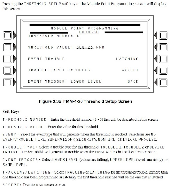
We are not going to get into too much detail on the programming of the FMM-4-20 module for the purpose of monitoring fire service access elevator lobbies, however, we have included a few notes and screenshots to show the setup and options.

Notifier Verifire Tools FMM-4-20 Programming
Notifier Verifire Tools with FMM-4-20 Module

CBE positions 3 - 7 are assigned to FMM-4-20 threshold levels 1 - 5 respectively. (Threshold levels are user-programmed. Refer to “FMM-4-20 Monitor Module Programming” on page 48 of the NFS2-3030 programming manual.) Each will activate only if the device is currently at that threshold level. Once the device leaves that threshold level, the zone in its corresponding CBE position will remain active or deactivate according to whether its threshold is programmed for latching or tracking.

Notifier FMM-4-20 Device Setup Programming

Notifier FMM-4-20 Threshold Setup Programming

Tuesday, December 20, 2016

Elevator Shunt Trip Wiring Diagram

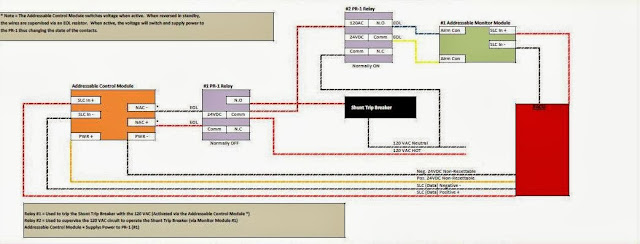
The below diagram is a sample of the fire alarm elevator shunt trip wiring method that is required by NFPA 72.  If you would like a copy of this document, please join our Facebook Group HERE and search the documents tab.

NFPA 72 Elevator Shunt Trip Wiring Connections

If you are interested in taking the NICET exam for fire alarms, then we have you covered! We are now selling our NICET Practice Tests Levels 1 - 4 practice exam with all the code references as to where to find the answers.  

Elevator Recall and Shunt Trip Basics

Here are the BASIC Fundamentals of Elevator Recall and Elevator Shunt Trip for Fire Alarm Systems.


With elevator technology changing every year, it is affecting the requirements of the fire alarm system.  Even with the addition of elevator control rooms and elevator closets, most of the fire alarm elevator recall service remains the same. Below are some key points as well as code/standard references to assist you in understanding the basics of elevator recall and elevator shunt trip with fire alarm systems.
    Elevator shaft with fire alarm
  • 1st Floor Elevator Lobby Smoke Detector (activates alternate level recall sending the elevator to the second floor)  NFPA 72 2016 21.3.13.2
  • 2nd Floor Elevator Lobby Smoke Detector (activates designated level recall sending the elevator to the first floor)  NFPA 72 2016 21.3.13.1
  • Elevator equipment room Smoke (if its on the designated recall level, it should send the elevator to the alternate recall level, if the room is on the alternate recall level, the smoke should send the elevator to the designated recall level)
  • Elevator equipment room Heat (Only required if the room is covered by automatic sprinklers) If this is the case, a heat detector shall be mounted within 2 feet of all sprinkler heads (NFPA 72 2016 Edition 21.4.2).  This heat detector will activate the elevator shunt trip function causing the elevator power to shut down.  Per NFPA 72 2016 the heat detector shall be set at both a higher sensitivity and lower temperature setting than the sprinkler heads.  This is so that the elevator power can be shut down before water is released on live (hot) equipment.  Note that a time delay must be in place to allow the elevator to travel from the top of the elevator hoistway to the lowest level of recall prior to shutting down the power (see NFPA 72 2016 Edition A.21.4.2)
  • Elevator shaft or hoistway.  If the top of the elevator hoistway or shaft is equipped with an automatic sprinkler head, you are required to install a smoke detector and a heat detector within 2 feet.  The smoke detector will recall the elevator to the first floor and the heat detector will activate the shunt trip as stated above.  Note that a time delay must be in place to allow the elevator to travel from the top of the elevator hoistway to the lowest level of recall prior to shutting down the power (see NFPA 72 2016 Edition A.21.4.2).  Also note that other methods can be used to achieve shunt trip function with elevators and fire alarm systems.  One way is to use a heat as specified above, two is to use a pre-action systems, and three is to use a waterflow/pressure switch.  If a waterflow or pressure switch is used for the shunt trip function of an elevator, there shall NOT be a delay (see NFPA 72 2016 Edition 21.4.3).  On top of that, the automatic sprinkler pipe branch has to be dedicated with its own ITV (inspectors test valve).  More information found here.
  • Elevator shaft or hoistway pit.  If there is an automatic sprinkler head located in the elevator pit remember this.  The head must be located higher than 2 feet off the bottom of the shaft in order to require any special requirements from the fire alarm system.  If the sprinkler head is located at 2 feet or lower, nothing is required on the fire alarm side.  Here is an article titled "Is a Heat Detector Required in the Elevator Pit".
  • Fireman's hat light.  You have probably seen it, it is a red light located at the elevator controls depicting the side profile of a fireman's hat.  This light needs to be programmed to activate (illuminate) if there is an activation of any fire alarm device in the elevator equipment room and or elevator shaft or hoistway.  This is in place to warn first responders that there is a fire in the elevator equipment room and or shaft so DO NOT OPEN!  See NFPA 72 2016 edition 21.3.13.3*
Now in today's world we have three different rooms we want to research before we layout the fire alarm devices required for a particular elevator recall system.  Below is a breakdown of these three rooms.
  • Elevator Machine/Equipment Room:  This is the standard room that we see on most projects. This room will house all of the actual elevator equipment, machines, motors, controls  etc.  In this room, we need to install the necessary relays for recall (primary and alternate as well as a relay for the fireman's hat light, smoke detection to cover the room space and heat detection if the area is is covered/protected by an automatic fire sprinkler system.
  • Elevator Control Room:  This is a smaller room that houses the controls for the elevators. This room will not contain the actual motors or machinery for the cars themselves.  The machinery and equipment will be located within the elevator shaft.  With that said, the
  • Elevator Closet:  This is a panel within the elevator shaft that houses all of the controls for the car's machinery.  Like the elevator control room, the closet is a clear indication that the machinery is located in the shaft.
Here is a sample elevator shunt trip wiring diagram article

Saturday, December 17, 2016

How to Wire Elevator Shunt Trip

Elevator Shunt Trip Wiring

We have created an easy to follow document for the proper wiring method with elevator shunt trip functions.  This document includes two methods both based on the supervision requirements of NFPA 72 2016 edition section A.21.4.4.

Below is a sample picture of the document that is available for download on our Facebook Group.

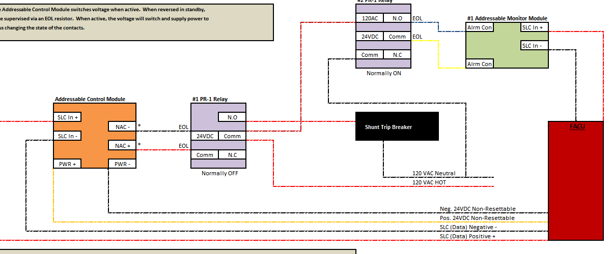
It is important to remember that the wiring between the FACP/FACU and the ECID (Emergency Control Interface Device) needs to be supervised.  In one method below, we are using an addressable relay module (FRM-1) to operate the shunt trip breaker directly.  With this wiring method, only the wire to the FRM-1 (SLC) needs to be supervised.  This is obviously achieved through the SLC and addressing of the device.


In the alternate method, we are showing you how to properly wire up the equipment when the load of the circuit exceeds the rating of the FRM-1.  In this case you would need to install a PR-1 interface relay (rated for 10 amps).  Now that you have a PR-1 switching the shunt trip circuit, this becomes your ECID (Emergency Control Interface Device) and the wiring up to this relay needs to be supervised.  To save the cost of an additional addressable monitor module (FMM-1) we can switch out the FRM-1 with a FCM-1 (addressable control module).  By doing this, we can achieve supervision as well as activation of the PR-1 interface relay through one device.


Elevator Shunt Trip Wiring Diagram


Make sure to download the document and let us know your thoughts.

Tuesday, March 24, 2015

Elevator Shunt Trip Requirements and Codes

Elevator Shunt Trip Explained

Elevator shunt trip wiring deta
Elevator Shunt Trip Wiring Detail
Elevator controls play a huge role in fire alarm system emergency functions. Whereas Designated and Alternate Elevator Recall captures and sends the elevator cab to safe floors, elevator shunt trip works a little different.  Elevator Shunt Trip is a function that involves shunting the breaker that controls the elevator equipment prior to the release of the automatic sprinkler systems.  This procedure is completed via the activation of heat detectors (addressable or conventional) connected to the building fire alarm system or dedicated function elevator control panel.  It is important to understand that not any heat detector within the facility will be required to activate the elevator shunt trip procedure.  The only heat detectors that will activate the elevator shunt trip control relay are those located in the elevator shaft or hoistway and elevator equipment room.

Group II and older elevators DO NOT have shunt trip

Group III and IV DO have shunt trip

Shunt Trip NOT permitted in Fire Service Access Elevators or Occupant Evacuation Elevators. 


What Specific Codes or Standards Address Elevator Shunt Trip?


The Fire Alarm and Signaling Code or NFPA 72 2016 section 21.4.2* states the following "If heat detectors are used to shut down elevator power prior to sprinkler operation, they shall be placed within 24 inches of EACH sprinkler head and be installed in accordance with the requirements of Chapter 17.  Alternatively, engineering methods, such as those specified in Annex B, shall be permitted to be used to select and place heat detectors to ensure response prior to any sprinkler head operation under a variety of fire growth rate scenarios.".

In order to ensure the elevator shunt trip control relay is activated prior to sprinkler head operation is addressed in NFPA 72 2016 section 21.4.1.  "Where heat detectors are used to shut down elevator power prior to sprinkler operation, the heat detector shall have both a lower temperature rating and a higher sensitivity compared to the sprinkler."

ASME A17.1 2013 "In jurisdictions not enforcing the NBCC, where elevator equipment is located or its enclosure is configured such that application of water from sprinklers could cause unsafe elevator operation, means shall be provided to automatically disconnect the main power supply to the affected elevator and any other power supplies used to move the elevator upon or prior to the application of water.  This means shall be independent of the elevator control and shall NOT be self-resetting."

Basically if there is potential for automatic fire sprinkler water to make its way onto the elevator controls or other power supplies for the elevator, there needs to be a way to shut down prior to this event.

Here are some "UNSAFE" conditions that can be caused by the automatic sprinkler system operation:

  • Elevator may react erratically due to water shorting out controls
  • Water on the elevator braking system
  • Risk of Shock or Electrocution
Also note that NFPA 13 and the International Building Code address when and where sprinklers will be used for elevator spaces.  In basic terms, sprinklers are not permitted in elevator spaces if the materials in these spaces are not combustible.  However, if there are combustible hydraulic fluid, coated belts, controls, etc. then sprinklers will be provided.  Just remember, No Sprinklers, No Shunt Trip.

We constantly get asked if you are required to install a heat detector in the bottom of the elevator shaft or elevator pit.  For more information on this topic, review our article titled "Is a Heat Detector Required in the Elevator Pit?"  

Can the Elevator Shunt Trip Activation be Delayed?


The answer is YES.  The activation of heat detectors can delay the elevator shunt trip via programming for a delay time not to exceed the time it takes the elevator cab starting at the top level to reach the lowest level of exit discharge.  The purpose behind this allowance is to increase the potential for elevators to complete their travel to the recall level.  Make note that the requirements of A17.1/B44 Safety Code for Elevators and Escalators would still apply.


If your fire alarm system utilizes waterflow or pressure switches to activate the elevator shunt trip, any time delay switches or capability will NOT be permitted per NFPA 72 2016 section 21.4.3.

Shunt Trip Control Circuits to be Monitored for Operating Voltage 


This is a step that seems to be missed a lot.  NFPA 72 2016 section 21.4.4 mentions that the control circuits used to shut down power to the elevator shall be monitored for the presence of operating voltage.  If the voltage is not present than a supervisory signal shall be indicated at the fire alarm control unit.

This activation can easily be accomplished with a PR-1 relay and addressable monitor module.  Power the PR-1 with the shunt trip control circuit and connect your addressable monitor module to the Common and Normally Open leads.  If the Control circuit loses power, the PR-1 will change state and short your IDC on the monitor module.  Program the module for tracking supervisory and label it "Shunt Trip Power".

What is the Requirement for Shunt Trip Breaker Location?


As of now, National Codes/Standard and Elevator Codes DO NOT indicate specific locations for the elevator shunt trip breaker.  However, in California the elevator shunt trip breaker must be installed OUTSIDE the elevator machine room (EMR).  The thought behind this is once the circuit is shunted, sprinkler activation can drip water over the breaker and return power to the elevator.

Resetting a Shunt Trip Breaker


When the shunt trip breaker is activated, the breaker switch itself will be between on and off.  To reset the breaker, make sure the controlling fire alarm system is reset and back to normal.  Once the FACU is reset, flip the shunt trip breaker all the way towards the off position (should be some tension) and then flick it all the way back to on.  

Thursday, March 19, 2015

Is a Heat Detector Required for the Elevator Pit

Designers are always asking, "Do I need to put a heat detector in the elevator pit?"

"Are you required to install a heat detector in the bottom of the elevator shaft otherwise known as the elevator pit?".  This is a question that comes up a lot in the fire alarm industry and often has system designers and AHJs (Authority Having Jurisdiction) scratching their heads.  Another related questions is, "Why is there a sprinkler head located at the bottom of the elevator shaft?".  A sprinkler head located in the bottom of the elevator pit is in place to control the spread of fire caused by the ignition of trash and debris that has fallen through the door opening and collected over time.

Heat Detector in Elevator PitThere are two items that need to be present before the requirement of a fire alarm system heat detector is required.  One is the presence of an automatic sprinkler head.  NFPA 13 2010 ed. 8.15.5 states that sprinklers heads are to be installed in the top and bottom of the elevator shaft.  There are exceptions to this rule so keep in mind that not all elevator shafts will incorporate a sprinkler head.  Two is the height in which the sprinkler head is installed off the floor of the elevator pit.  ASME A17.1 states that if a sprinkler head is installed within 24" (2 feet) of the elevator pit floor, it shall be exempt from the special arrangements of inhibiting water flow until the elevator recall function has occurred.

A heat detector is required to be installed within 2' of any sprinkler head associated with shutting down the power to an elevator (NFPA 72 2016 ed. 21.4.2*). It is important to shut down the elevator power prior to the release of water from a sprinkler head since water and electronics do not mix.  This is the reason the heat detector is required to be set to a lower temperature setting and higher sensitivity setting than the sprinkler head (NFPA 72 2016 ed 21.4.1*). With that said, a heat detector is not required if the sprinkler head is located within 24" of the elevator pit floor since there is typically not any electrical components located in this area.


There are three common methods to shutting down the main elevator power prior to water flowing from a sprinkler head in the shaft or elevator machine room.


#1) The most economical method is to use a waterflow switch.  Upon activation, the waterflow switch would cause an alarm at the FACU (Fire Alarm Control Unit) as well as activate the shunt trip breaker causing the power to be interrupted.  Make sure you follow NFPA 72 2010 ed 21.4.3*.  This code section states that if using waterflow or pressure switches to shut down elevator power, the use of a time delay shall not be permitted.

#2) This is the most common method.  By use of a fixed temperature rate of rise heat detector located within 2' of each sprinkler head in the shaft, hoistway or elevator machine room.  The heat detector shall be set to a lower temperature than the sprinkler head and when activated, will cause an alarm at the FACU and shunt the breaker associated with powering the elevator.

#3) Use of a pre-action system.  These systems would have supplemental fire detection devices installed in the same areas as the sprinkler heads.  Make note that the detection devices should be heat detectors.  Once on of the heat detectors have been activated, it would tell the pre-action control panel through program mapping to open a valve control by a solenoid.  Once the valve is open, water would then fill the sprinkler system piping in the elevator hoistway and elevator equipment room.  At the same time, the heat detector would also trip the shunt breaker thus shutting down the elevator power.  If a fire really is present in these areas, it would eventually fuse the sprinkler head and release water to the affected area.

Keep in  mind that heat detectors are to be used for shutting down power to the elevator and not smoke detectors.  Smoke detectors associated with elevators are to be solely used for designated elevator recall, alternate elevator recall and to activate the elevator hoistway smoke relief equipment.