Saturday, December 31, 2016

Voice Intelligibility for Accurate Occupant Notification

Voice Intelligibility for Clear Evacuation Message
Do you know the reason behind modern fire alarm systems?  They are intended to recognize a potential life threatening fire situation such as smoke, flame or heat.  It is then their responsibility to alert the masses.  If the whole point to a fire alarm system is to alert and inform occupants, then what good does it do if these occupants can not understand the evacuation message?  This is what prompted the National Fire Protection Association or NFPA to change the title of NFPA 72 from the National Fire Alarm Code to the National Fire alarm and Signaling Code first seen in the 2010 edition.

Side note:  Did you know that NFPA 72 is not a Code reference rather a Standard?  Learn more in this article title Fire Alarm Codes vs. Standards.

I am sure seasoned fire alarm system designers have had this pounded into their heads by now but news flash, fire alarm notification signals are no longer the priority in some scenarios.  We have always been taught that our occupant notification alert or evacuation messages were to take precedence over any other audio or tone.  To an extent this is still correct including outputs such as Musak, Public Address or P.A.,  Concert or Performance Audio, etc.  There are now and have been for some time, fire alarm systems incorporating additional features that make up what is known as Mass Notification.  The alert tones, voice messages and canned message instructions of a mass notification system are to take priority over any fire alarm notification output.  This was the reason behind the revision and extended title of NFPA 72.  The National Fire Protection Association added the word "Signaling" to the title of NFPA 72 as well as chapter 24 covering Emergency Communication Systems (ECS).  NFPA 72 does not cover every aspect of Mass Notification system design.  If you are seeking additional information on the requirements of these systems, you will need to obtain a copy of the Unified Facilities Criteria (UFC) document titled "Design and O&M: Mass Notification Systems"

If you research the document above, you will become aware that Mass Notification adds a lot of new criteria to the design and engineering of a given fire alarm system, however this article will serve to inform readers on the importance of a term known as Voice Intelligibility.  If you consult the Annex D of your 2013 NFPA 72 (starts on page 311) you will find all the information pertaining to voice intelligibility.  Below we are going to touch on some of the important factors to keep in mind when up against a mass notification system that must meet specified voice intelligibility measurements.

    voice intelligibility can you hear me now
  1. What exactly is voice intelligibility?  Voice intelligibility is a measure of how comprehensible speech is in given conditions.  Voice Intelligibility is affected by the quality of speech signal, the type and level of background noise, reverberation, and for speech over communication devices, the properties of the communication system.  The concept of voice intelligibility is relevant to several fields, including phonetics, human factors, acoustical engineering and audiometry.
  2. In order to meet the criteria of NFPA 72 as well as the UFC, you will need to have what is known as a risk analysis drafted up by a fire protection engineer.  A risk analysis is an individual plan for a specific facility.  This plan includes a multitude of criteria based on potential risks and threats at the given facility.  This risk analysis will breakdown segregated areas of the building and how to evacuate or hold occupants based on individual threatening scenarios.  The risk analysis will also explain acoustically distinguishable spaces or ADS.  As defined by NFPA 72 2016 D.2.3.1.1 - An acoustically distinguishable space can be an emergency communication system notification zone, or subdivision thereof, that can be enclosed or otherwise physically defined space, or that can be distinguishable from other spaces because of different acoustical, environmental, or use characteristics such as reverberation time and ambient sound pressure level.  The ADS might have acoustical design features that are conductive for voice intelligibility, or it might be a space where voice intelligibility could be difficult or impossible to achieve.
  3. Once evacuation or staging areas of the facility are understood, we will need to design the audio potion of the mass notification system.  This is where voice intelligibility comes into play.  Keep in mind the differences between audibility levels (dB) and Voice Intelligibility.  For lack of better terms, one defines the sound pressure and the other defines the clarity and comprehension of the audio.  Just because you meet the intent of NFPA 72 chapter 18 in regards to dB levels does not mean you have accomplished an acceptable measurement of voice intelligibility.
  4. How do you measure voice intelligibility?  Unlike the use of a dB meter for audibility, voice intelligibility is a little more tricky.  There are two scales used to measure intelligibility.  One is the CIS scale which stands for Common Intelligibility Scale and the other is STI or Speech Transmission Index.  To acquire this reading you will need..... You guessed it, a Voice Intelligibility meter.   
  5. What is a passing measurement for voice intelligibility?  The voice intelligibility of an emergency communication system is considered acceptable if at least 90 percent of the measurement locations within each ADS have a measured STI of not less than 0.45 (0.65 CIS) and an average STI of not less than 0.50 (0.70 CIS).  The measurement shall be taken from an elevation of 5 feet or any other elevation deemed appropriate based on occupancy.  In areas of the facility where sound levels exceed 90 dB, it may be impossible to meet these voice intelligibility measurements.  In these cases other methods such as LED signage, etc. may be used.  For reference the STI scale can be converted to CIS via the following calculation:  CIS = 1 + log (STI).
voice intelligibility meter CIS scale and STI scale


There are a ton of factors to take in when designing a mass notification system to meet the voice intelligibility requirements of NFPA 72 and the Unified Facilities Criteria.  This article is meant to touch on the main points and get you going in the right direction.

If you are in the market for a dependable voice intelligibility meter, I highly recommend the VOX01 from SDi.  This unit is compact, sturdy, very easy to use and comes packed with tons of features and abilities.  Here is a direct link to SDi's webpage containing information on the VOX01.  Below is a video of me revealing the VOX01 when it first came to market.  Feel free to check it out and let us know if you have any questions.  


Fire Alarm Codes vs. Standards

What is the difference between fire alarm codes and fire alarm standards?

The terms "code" and "standards" are commonly used to represent the same thing.  However, the two terms stand for completely different meanings.  Fire alarm codes are written rules and regulations that are then adopted as law for enforcement by an AHJ or Authority Having Jurisdiction.  Fire alarm codes once put in place, are the minimum requirements that must be complied with to provide a reasonable degree of life safety. Codes are written based on standards.  Fire alarm standards are generally produced by a consensus or technically committee to represent a minimum level of how to install certain types of protection.  Standards are focused on one particular system component and give guidelines on the proper installation, maintenance and inspecting.

NFPA 101 Life Safety Code Book
Fire Alarm Code:

Fire alarm codes specify when and where a given type of protection is required.  These fire alarm codes are a minimum requirement and are encouraged to be exceeded.  Below is a list of fire alarm and fire related code references:
  • NFPA 30 (Flammable and Combustible Liquids Code)
  • NFPA 54 (National Fuel Gas Code)
  • NFPA 70 (National Electrical Code)
  • NFPA 101 (Life Safety Code)
  • NFPA 5000 (Building Construction and Safety Code)
  • IBC (International Building Code)
  • IFC (International Fire Code)
Fire Alarm Standard:

Fire alarm standards detail how a specific protection required by the code is to be achieved.  Below is an example list of fire alarm and fire related standards:
  • NFPA 10 (Standard for Portable Fire Extinguishers)
  • NFPA 13 (Standard for the Installation of Sprinkler Systems)
  • NFPA 14 (Standard for the Installation of Standpipes and Hose Systems)
  • NFPA 20 (Standard for the Installation of Stationary Pumps for Fire Protection)
  • NFPA 72 (National Fire Alarm and Signaling Code)*
*  Keep in mind that NFPA 72 tells us how to install fire alarm systems.  It doesn't explain what type of equipment (pull stations, smoke detectors, duct detectors, waterflows, tampers) should be used.  This information can be found in the specific jurisdiction's adopted building code.

How you determine the Fire Alarm requirements.

Check with your local authority having jurisdiction to determine what edition of the applicable codes they are currently enforcing.  Most codes will determine the fire alarm and automatic fire sprinklers based on the occupancy classifications of the particular building.  If NFPA 101 Life Safety Code is enforced, consult section 9.6 for the exact system installation requirements.

Tuesday, December 20, 2016

Low Frequency Sounders for Fire Alarm Evacuation


Are Low Frequency Sounders Being Enforced by your AHJ


Is your jurisdiction enforcing the new code mandated 520 Hz low frequency sounders for fire alarm audibility yet?  If so how are you tackling this new requirement?  And finally did you know that the smoke alarms within the sleeping rooms and guest units do not need to meet the 520 Hz requirement?

When did this start?

System Sensor Low Frequency Sounder and Sounder StrobeNot a lot of people are aware that this requirement was originally noted in the (2010) NFPA 72 National Fire Alarm Code section 18.4.5.3.  It states "Effective January 1, 2014, where audible appliances are provided to produce signals for sleeping areas, they shall produce a low frequency alarm signal that complies with the following:
(1) The alarm signal shall be square wave or provide equivalent awakening ability.
(2) The wave shall have a fundamental frequency of 520 Hz +/- 10 percent.

Now we fast forward to 2013.

Note that the (2013) NFPA 72 Fire Alarm and Signaling Code requirements are the same found in Section 18.4.5.3

Now lets break it down.  There are a lot of code sections so stay with me.

The Annex A of NFPA 72 (2013) section A18.4.5.3 lets us know that this section does not cover the audible requirements of single and multiple station smoke alarms and instructs us to consult chapter 29 for said requirements.

If you refer to Chapter 29 "Single and Multiple-Station Alarms and Household Fire Alarm Systems" section 29.3.6 it states the following: "All audible fire alarm signals installed shall meet the performance requirements of 18.4.3, 18.4.5.1, 18.4.5.2 and 29.3.8."  Please notice that this section does not include section 18.4.5.3. This may lead one to believe that single and multiple station smoke alarms for dwelling units do not need to meet the new 520 Hz low frequency requirements.

The key section to pay attention to here is section 29.3.8 which states "Notification appliances provided in sleeping rooms and guest rooms for those with hearing loss shall comply with 29.3.8.1 and 29.3.8.2, as applicable."

Section 29.3.8.1 "Mild to Severe Hearing Loss.  Notification appliances provided for those with mild to severe hearing loss shall comply with the following:

(1) An audible notification appliance producing a low frequency alarm signal shall be installed in the following situations:

    (a) Where required by governing laws, codes, or standards for people with hearing loss.
    (b) Where provided voluntarily for those with hearing loss.

(2) The low frequency alarm signal output shall comply with the following:

    (a) The waveform shall have a fundamental frequency of 520 Hz +/- 10 percent.
    (b) The minimum sound level at the pillow shall be 75 dba, or 15 dba above the average ambient sound level or 5 dba above the maximum sound level having a duration of at least 60 seconds, whichever is greater."

Section 29.3.8.2 "Moderately Severe to profound Hearing Loss.  Visible notification appliances in accordance with the requirements of 18.5.5.7 and tactile notification appliances in accordance with the requirements of section 18.10 shall be required for those with moderately severe to profound hearing loss in the following situations:

(1) Where required by governing laws, codes, or standards for people with hearing loss.
(2) Where provided voluntarily for those with hearing loss.

What does this mean?  


Low frequency sounder internal view speaker coneIf we read section 29.3.8 very carefully you will notice the word "AND" between sleeping rooms and guest rooms for those with hearing loss.  This is telling us that the requirements of section 29.3.8.1 and 29.3.8.2 apply to ALL sleeping rooms including guest rooms for those hard of hearing.

How does this effect your design?

To this date there are no UL listed UBC smoke alarms that can produce an audible tone at 520 Hz.  In fact the only manufacture that has a UL listed 520 Hz low frequency sounder appliance is System Sensor.  This means no more mini horns in the sleeping rooms of R-1, R-2 and R-2.1 occupancies.  The only way to accomplish this is by installing a System Sensor HW-LF (low frequency sounder) or addressable smoke detector with low frequency sounder base in place of all mini horns.  This will give us the required 520 Hz in all sleeping areas during a general alarm condition.

How do we accomplish 520 Hz when the Single or multiple station smoke alarm is activated?

Since there is no such thing as a low frequency LISTED smoke alarm, I propose installing addressable system smoke detectors in all sleeping rooms and guest rooms.  On top of this an addressable control module will need to be installed for each residential unit.  The control module will then need to be wired so that it controls an individual NAC (Notification Appliance Circuit) for that particular unit.  Through programming we can activate this individual control module upon activation of any smoke detectors within the unit.  Lastly the control module for each unit will need to be mapped to activate during a general alarm condition.  This way we are activating the in room low frequency sounders via the in room smoke detectors as well as any building wide general alarm device.  This method allows us to accomplish the requirements of section 18.4.5.3 as well as 29.3.8 with listed equipment and methods.

How does this effect your final cost?

Obviously there is a lot more equipment needed to perform this requirement such as addressable system smokes and control modules.  On top of this the low frequency sounders are more expensive than mini horns.  Also note that the new low frequency sounders draw more current than mini horns which will decrease your total allowable appliances per NAC ultimately increasing the number of required remote power supplies.

This is going to be a huge adjustment for our industry which will ultimately comes with a large learning curve.  I suggest your contact your local AHJ (Authority Having Jurisdiction) and find out what their interpretations on this subject are.

Reading Reverse Polarity with a Meter

Do you know how to Use a Multi Meter to Locate a Fire Alarm Device or Appliance that has been connected with reverse polarity?

If not this article will explain how to set the multi meter up as well as how to properly break down fire alarm circuits to locate an initiating device and or notification appliance that has been connected with reverse polarity.

Real quick we will start with the basics.  "What is polarity?"  Polarity in electrical circuits is known as "Positive" and "Negative".  In DC (Direct Current) circuits one pole is always positive (typically marked with a + or red) and the other is always negative (typically marked with - or black).  Note that electrons within a DC circuit only flow in one direction.

This is where a lot of people become confused.  There are two common notations of flow for DC circuits. See below:

#1 is the Conventional Flow Notation.  This notation is based on Benjamin Franklin's conjecture regarding the flow direction of charge.  This notation shows charge flow moving from the Positive Pole of a DC circuit to the Negative Pole.  This is the notation that is most commonly used my engineers and is technically incorrect.

#2 is the Electron Flow Notation.  This is the true notation of charge flow as it shows the actual motion of the electrons in a DC circuit.  Note that this notation shows the charge flow moving from the Negative Pole to the Positive Pole. 

Now that we have covered how a charge or current flows through a circuit, it is important to understand how a diode works and how it can allow or block this flow from occurring.

Definition of a DIODE: A semiconductor device with two terminals, typically allowing the flow of current in one direction only.  This direction of current flow moves from the ANODE side through the CATHODE side of the DIODE.  An easy way to remember this is a DIODE allows current to flow in the direction of the arrow within the symbol.

Here is the electrical symbol for a DIODE:

DIODE showing the Anode and Cathode Orientation


Below are two diagrams that depict the same image however they show the current flowing in opposite directions (conventional vs. electron flow notation).  Notice that even though they both have a diode facing in the same direction the lamp is still illuminated.  "Why is this?"  I thought that a diode only allows current to flow in one direction and that a DC circuit only flows in one direction.  "This would make it impossible to illuminate the lamp in both scenarios, right?"

Conventional Flow Notation with Diode and Lamp
Conventional Flow Notation with DIODE
Electron Flow Notation with Diode and Lamp
Electron Flow Notation with DIODE
         
This is correct.  However the symbol for a DIODE has never been updated to match the Electron Flow Notation.  Therefor the DIODE is always shown with the "Line" or Cathode side pointing towards the positive flow based on the Conventional Flow Notation.  Note that if we were to update the DIODE symbol and show the arrow facing the opposite direction, the diagram based on the Electron Flow Notation would make more sense.

Now on to the point of this article.  "How do I use this information regarding current flow and diodes to locate a fire alarm device or notification appliance that has been connected with reverse polarity?"

A fire alarm initiating device or notification appliance that is polarity sensitive meaning it must be connected with the correct input (positive/negative) will have an internal DIODE to restrict the current flow in one direction as stated above.  We can use the diode setting on our Multi Meter to locate any section of a fire alarm circuit that has been connected backwards or with Reverse Polarity.

How it works:  When you select the DIODE setting your Multi Meter will force a small amount of current through the DIODE and measures the voltage drop across your Multi meter test leads.

Forward Bias Diodes:  If you have the Positive test lead connected to the Anode side and the Negative test lead connected to the Cathode side of the DIODE, your Multi Meter should display something close to 0.548 Volts.

Reverse Bias Diodes:  If you have the Positive test lead connected to the Cathode side and the Negative test lead connected to the Anode side of the DIODE, your Multi Meter should display OL (Open Line).

Multi Meter DIODE Test for Reverse PolarityI suggest testing a single device/appliance on a specific circuit prior to searching for reverse polarity on a fire alarm run. This can be accomplished by using a spare or by taking down a device on a circuit you need to test.  Once you have the fire alarm device or notification appliance removed, place your positive (red) multi meter test lead on the positive terminal of the equipment and the negative (black) multi meter test lead on the negative terminal of the equipment.  If your multi meter displays 0.548 Volts then you have a circuit with Forward Bias Diodes.  If your multi meter displays OL then your circuits has Reverse Bias Diodes.

Here is the key to the puzzle.  If you test the wire in your circuit and your meter displays a dead short (0.000 and typically sounds a steady beep) then your circuit has one or more devices wired backwards.  This is known since diodes in Forward and Reverse bias positions would allow the current in your circuit to travel in both directions ultimately resulting in a dead short.

Now that you know which orientation your circuit's diodes face, you can start breaking down the circuit in halves.  Each time you cut the circuit in half, read the wires in both directions paying attention to multi meter's display looking for either 0.548 V, OL or a dead short.

This easy to use Multi Meter trick will help you eliminate very time consuming labor when troubleshooting fire alarm circuits.

How to Use a Multi-Meter for Fire Alarm

Multi Meter Basics

One of the most important tools a fire alarm technician posses is the digital voltmeter or digital multi meter.  This article will explain the different settings and how they can help you track down important circuit information such as end of line resistance values, current draw, reverse polarity, dead shorts, ground faults, AC inductance and capacitance.

I cannot stress enough the importance of purchasing a quality voltmeter or multi meter.  For the purpose of the this article I will be utilizing a Fluke 117.  This is a high end meter that won't break the bank.  It has all of the key settings including a back-light for dark spaces as well as non-contact voltage detection.  In case you did not catch that last one, it will detect high and low AC voltage just by simply holding the meter close to the source.

FLUKE 117 Multi-Meter for Fire Alarm Troubleshooting


You can read more about this powerful true-rms multi meter here.

In this article we will show you how to properly tune the voltmeter or multi meter to the correct settings as well as when to move the test leads depending on what circuit information you are trying to obtain.

Now it is important to explain the different symbols and buttons so that you better understand how to navigate through this information.

Please note that although I am referencing the Fluke 117, these symbols should be close to the same on any multi meter you are using in the field.

Multi Meter Buttons and Functions:


"HOLD" This button will hold the display at the current view for documentation at a later time.  As you may know, the multi meter display may fluctuate from time to time so this button can prove to be useful if you want to lock it in at a particular time.

"MIN/MAX" As stated above the multi meter display will fluctuate between higher to lower readings.  This button can be pressed to either lock in the lowest/minimum or the highest/Maximum reading. Also note that on this meter, there is another selection with this button that will display the average between the minimum and maximum.

"RANGE" This multi meter has both manual and auto-ranging modes.  In auto-range mode the meter will automatically select the range with the best resolution.  In manual mode you must use this button to cycle through the different ranges whether it be for resistance, voltage, current capacitance, etc.

"YELLOW BUTTON" the yellow button on this meter is like a shift key.  It will allow you to select the yellow options located on the rotary wheel.

Below is a list of the most important multi meter modes and what they can be used to test for.  Feel free to click on the separate links to read further on these topics:  Please note the picture below is of a FLUKE 115 which is basically the same as the 117 minus the AUTO-V LoZ and Volt Alert settings.
FLUKE 115 Multi-Meter Settings and Uses

Selections via Multi meter Rotary Wheel:


"AUTO-V LoZ" Automatically selects ac or dc volts based on the sensed input with a low impedance input.
AC voltage from 0.06 to 600 V.
DC voltage from .001 to 600 V.

AC voltage from 6.0 to 600 mV
DC voltage from 0.1 to 600 mV

Learn More About Reading for Voltage on Fire Alarm Circuits Here.

Ohms from 0.1 ohms to 40 milliohms
Continuity beeper turns on at less than 20 ohms and turns off at greater than 250 ohms.

Learn More About Reading for End of Line Resistance, Ground Faults, Shorts and Continuity on Fire Alarm Circuits Here.

Diode test.  Displays OL (Open Line) above 2.0 V.

Learn More About Reading for Reverse Polarity on Fire Alarm Circuits Here.

Farads from 1 nF to 9999 micro Farads

Learn More About Reading for Capacitance on Fire Alarm Circuits Here.

AC current from 0.1 A to 10 A.
DC current 0.1 A to 10 A.

Learn More About Reading Current on Fire Alarm and Control Circuits Here.

"Volt Alert" Non-contact sensing of ac voltage.

Reading Electrical Current with a Meter

As you may know, fire alarm control equipment has current ratings and limitations.  For example, an addressable relay module from Notifier (FRM-1) has the following current limitations:

3 Amps @ 30 VDC Resistive Non-Coded
2 Amps @ 30 VDC Resistive Coded
.9 Amps @ 125 VAC Resistive Non Coded

This is letting us know that if we need to switch a 30 volt DC (Direct Current) circuit through this relay, we must be below 3 amps (for Non-Coded) and 2 amps for (Coded).

There are two ways to find out if we are below this number.

#1) Read the data sheets and instruction manuals of the equipment that is being powered by this circuit.  These informational sheets should have the current load numbers for your use.  Add this number up by the quantity of equipment to be powered and you should have a number close to reality.  I do not recommend this as you may end up calculating a number lower than actuality therefor jeopardizing the fire alarm relay.

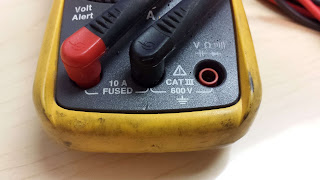
#2) With the proper use of a Multi Meter we can get an exact current reading from any circuit (as long as it is energized).  Now keep in mind that Multi Meters have limitations on the current that can read as well.  For example the Multi Meter we are using for this example has a 10 A fused limit for reading AC/DC current. Read below to find out how to set your Multi Meter up for reading current.

Before we continue please know the difference between a series circuit and a parallel circuit.  In order to measure the load or current of a fire alarm circuit, we must place the Multi Meter test leads in SERIES with the circuit to be read.  This is very important as it is impossible to do otherwise.  Also note that you will need to move the positive test lead to the Amp test lead port as shown in the pictures below:

Fluke meter voltage and continuity probe setup
This picture shows the Fluke 117 Multi Meter with the test leads in the normal position to meter for voltage, resistance, capacitance, etc.


Fluke meter current probe setup
This pictures shows the Fluke 117 Multi Meter with the positive test lead moved over to the Amp port.  This is mandatory when checking a fire alarm circuit for current.


Now as we stated above you need to place the Multi Meter test leads in series with the circuit being read. For example:  If you have a relay with one leg landed on the C (Common) terminal and the other leg landed on the NC (Normally Closed) terminal your circuit is complete and the equipment being controlled should be functional.  If you pull the wire leg off of the Common terminal, the equipment should stop.

Before we connect the Multi Meter to the circuit we need to insure we have the meter on the correct setting. Be aware if you are reading an AC or DC circuit and select the appropriate setting as noted in our previous article discussing Multi Meter basics.

Now with the wire disconnected from the Common terminal, land your negative (black) test lead on the Multi Meter to that same terminal on the relay.  Now we need to complete the circuit to get an accurate current reading.  Land the positive (red) test lead on the multi meter to the wire leg you disconnected from the Common terminal.  If done correctly the equipment should power back up and your Multi Meter will display the total current of that circuit.

Below are a couple of pictures showing how the Multi Meter test leads should be connected to the circuit to properly read for current.  Please note that the circuit used in these pictures is an SLC connected to a Notifier NFS2-3030 branching off to five FCM-1 addressable control modules.


Fire Alarm SLC Connection on Terminal Strip
SLC Connection on Terminal Strip

Fire Alarm SLC disconnected for current reading
SLC On Terminal Strip with Negative Conductor Disconnected for Current Reading

Reading Fire Alarm Circuit for DC Current with FLUKE 115
Meter probes to make continuity between terminal and disconnected wire


Fluke Amp Clamp Attachment for Multi MetersIf this is not something you feel comfortable with, then Fluke has you covered.  Below is a picture of a current reading clamp that they make for their Multi Meters.  All you need to do is plug it into your Fluke Multi Meter and clamp the spring loaded clamp around one leg of the circuit.  This way you do not need to disconnect any live circuits.


Also note that relays are not the only application where you might need to take a current reading on fire alarm circuits.  Other example applications may include NAC (Notification Appliance Circuits), Door Holder circuits, Magnetic Door Locks, etc.  Always remember that you need to verify that you are not over-loading the circuit based on the limitation set forth in the data sheets and instructions manuals.

This concept is no different that your house.  If you plug too many electronics into electrical outlets on one 120 VAC circuit then you are going to pop the breaker.  These limitations are put in place for the protection of the equipment as well as your personal safety.

Elevator Shunt Trip Wiring Diagram

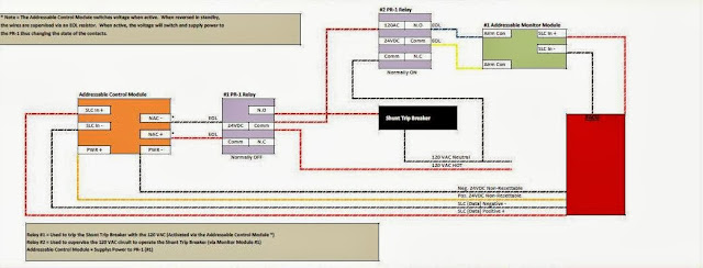
The below diagram is a sample of the fire alarm elevator shunt trip wiring method that is required by NFPA 72.  If you would like a copy of this document, please join our Facebook Group HERE and search the documents tab.

NFPA 72 Elevator Shunt Trip Wiring Connections

If you are interested in taking the NICET exam for fire alarms, then we have you covered! We are now selling our NICET Practice Tests Levels 1 - 4 practice exam with all the code references as to where to find the answers.  

Elevator Recall and Shunt Trip Basics

Here are the BASIC Fundamentals of Elevator Recall and Elevator Shunt Trip for Fire Alarm Systems.


With elevator technology changing every year, it is affecting the requirements of the fire alarm system.  Even with the addition of elevator control rooms and elevator closets, most of the fire alarm elevator recall service remains the same. Below are some key points as well as code/standard references to assist you in understanding the basics of elevator recall and elevator shunt trip with fire alarm systems.
    Elevator shaft with fire alarm
  • 1st Floor Elevator Lobby Smoke Detector (activates alternate level recall sending the elevator to the second floor)  NFPA 72 2016 21.3.13.2
  • 2nd Floor Elevator Lobby Smoke Detector (activates designated level recall sending the elevator to the first floor)  NFPA 72 2016 21.3.13.1
  • Elevator equipment room Smoke (if its on the designated recall level, it should send the elevator to the alternate recall level, if the room is on the alternate recall level, the smoke should send the elevator to the designated recall level)
  • Elevator equipment room Heat (Only required if the room is covered by automatic sprinklers) If this is the case, a heat detector shall be mounted within 2 feet of all sprinkler heads (NFPA 72 2016 Edition 21.4.2).  This heat detector will activate the elevator shunt trip function causing the elevator power to shut down.  Per NFPA 72 2016 the heat detector shall be set at both a higher sensitivity and lower temperature setting than the sprinkler heads.  This is so that the elevator power can be shut down before water is released on live (hot) equipment.  Note that a time delay must be in place to allow the elevator to travel from the top of the elevator hoistway to the lowest level of recall prior to shutting down the power (see NFPA 72 2016 Edition A.21.4.2)
  • Elevator shaft or hoistway.  If the top of the elevator hoistway or shaft is equipped with an automatic sprinkler head, you are required to install a smoke detector and a heat detector within 2 feet.  The smoke detector will recall the elevator to the first floor and the heat detector will activate the shunt trip as stated above.  Note that a time delay must be in place to allow the elevator to travel from the top of the elevator hoistway to the lowest level of recall prior to shutting down the power (see NFPA 72 2016 Edition A.21.4.2).  Also note that other methods can be used to achieve shunt trip function with elevators and fire alarm systems.  One way is to use a heat as specified above, two is to use a pre-action systems, and three is to use a waterflow/pressure switch.  If a waterflow or pressure switch is used for the shunt trip function of an elevator, there shall NOT be a delay (see NFPA 72 2016 Edition 21.4.3).  On top of that, the automatic sprinkler pipe branch has to be dedicated with its own ITV (inspectors test valve).  More information found here.
  • Elevator shaft or hoistway pit.  If there is an automatic sprinkler head located in the elevator pit remember this.  The head must be located higher than 2 feet off the bottom of the shaft in order to require any special requirements from the fire alarm system.  If the sprinkler head is located at 2 feet or lower, nothing is required on the fire alarm side.  Here is an article titled "Is a Heat Detector Required in the Elevator Pit".
  • Fireman's hat light.  You have probably seen it, it is a red light located at the elevator controls depicting the side profile of a fireman's hat.  This light needs to be programmed to activate (illuminate) if there is an activation of any fire alarm device in the elevator equipment room and or elevator shaft or hoistway.  This is in place to warn first responders that there is a fire in the elevator equipment room and or shaft so DO NOT OPEN!  See NFPA 72 2016 edition 21.3.13.3*
Now in today's world we have three different rooms we want to research before we layout the fire alarm devices required for a particular elevator recall system.  Below is a breakdown of these three rooms.
  • Elevator Machine/Equipment Room:  This is the standard room that we see on most projects. This room will house all of the actual elevator equipment, machines, motors, controls  etc.  In this room, we need to install the necessary relays for recall (primary and alternate as well as a relay for the fireman's hat light, smoke detection to cover the room space and heat detection if the area is is covered/protected by an automatic fire sprinkler system.
  • Elevator Control Room:  This is a smaller room that houses the controls for the elevators. This room will not contain the actual motors or machinery for the cars themselves.  The machinery and equipment will be located within the elevator shaft.  With that said, the
  • Elevator Closet:  This is a panel within the elevator shaft that houses all of the controls for the car's machinery.  Like the elevator control room, the closet is a clear indication that the machinery is located in the shaft.
Here is a sample elevator shunt trip wiring diagram article

Monday, December 19, 2016

Smoke Detectors for HVAC Shutdown

"For fire smoke dampers, should I use an in-duct spot type smoke detector or a duct detector?"

Sampling tube style duct detectors are listed for a minimum air velocity of 100 fpm (feet per minute). If you are to ensure the rating of the wall at duct penetrations (dampers), you must provide coverage per The International Building Code IBC 2021 Edition Section 717.3.3.2.  

717.3.3.2 Smoke damper actuation. The smoke fire damper shall close upon actuation of a listed smoke detector or detectors installed in accordance with Section 907.3 and one of the following methods, as applicable:

1. Where a smoke damper is installed within a duct, a smoke detector shall be installed in the duct within 5 feet (1524 mm) of the damper with no air outlets or inlets between the detector and the damper. The detector shall be listed for the air velocity, temperature and humidity anticipated at the point where it is installed. Other than in mechanical smoke control systems, dampers shall be closed upon fan shutdown where local smoke detectors require a minimum velocity to operate.

2. Where a smoke damper is installed above smoke barrier doors in a smoke barrier, a spot-type detector listed for releasing service shall be installed on either side of the smoke barrier door opening.

3. Where a smoke damper is installed within an air transfer opening in a wall, a spot-type detector listed for releasing service shall be installed within 5 feet (1524 mm) horizontally of the damper.

4. Where a smoke damper is installed in a corridor wall or ceiling, the damper shall be permitted to be controlled by a smoke detection system installed in the corridor.

5. Where a total-coverage smoke detector system is provided within areas served by a heating, ventilation and air-conditioning (HVAC) system, smoke dampers shall be permitted to be controlled by the smoke detection system.

The 1st method above states that you must provide a smoke detector installed in the duct within 5’ of the fire smoke damper, and that the smoke detector shall be listed for the air velocity.  If you shut down the fan, there will not be a minimum air velocity of 100 fpm to achieve the proper listing of a sampling tube style duct detector (System Sensor D4120 for example).  Notice that this same paragraph states that “Other than in mechanical smoke control systems, dampers shall be closed upon fan shutdown where local smoke detectors require a minimum velocity to operate”.

What if we decide to use sample tube duct smoke detectors?


System Sensor D4120 Sample Type Duct DetectorIf we are using duct detectors for damper control, then whenever the fan is off, the dampers must be shut since the duct detectors such as the System Sensor D4120 require a minimum velocity of 100 fpm to operate.  Does this mean we then have to monitor fan status, and shut dampers upon fan shutoff, or shall the mechanical contractor have to inter-tie with all the dampers associated with that fan?  If we decide to monitor the fan, that creates another issue—per the IMC (International Mechanical Code), if a damper has automatically been activated to close, the associated fan must be shutdown.  Picture this scenario—AHU1 turns off, so we shut down the dampers.  The damper circuit we are controlling also serves dampers associated with AHU2, therefore we must shut that one down as well.  Since AHU2 is serving other areas of the building, we must shut those circuits of dampers as well, and so on until the whole building has typically been shut down for HVAC equipment including dampers.

What if we use spot type In-Duct Smoke Detectors?


In-Duct Smoke Detector Spot TypeOn the other hand, if we are protecting the fire smoke dampers with an in-duct detector, you can have the fan shut down upon duct detector for the fan, and the dampers throughout the rest of the building may remain open and the other fans may remain on.  The damper is still protected with the in-duct smoke detector to ensure the rating of the wall to shut the damper upon detection of smoke, and if the in-duct smoke detector activates, then we go through the shut-down process of the fans and dampers throughout the building as exampled above.  Note that in-duct detectors have a listed minimum air velocity of 0 fpm, meaning that it does not “require a minimum velocity to operate“, therefore not requiring shutdown of the building upon a single fan being shut down.

Building owners really don’t like when their building heats up because they are servicing one of their fans, or one of the many fans in their building turns off due to a number of circumstances that are not necessarily indicative of a fire, and our fire alarm system shuts down all HVAC movement in the building.  Mechanical contractors don’t like it when they are forced to interface with individual dampers to close upon fan shutdown.  And finally, electrical/mechanical contractors really don’t like it when we force them to give us a true status of the fan via a Current or Differential Pressure switch when the fan is not a part of a smoke control system and it was not shown on their drawings or bid docs.

If you like what you see here then make sure to join our Facebook Group here.

Fire Damper vs. Fire Smoke Damper

Do you know the difference between fire dampers and fire smoke dampers?

This is a questions that seems to come up a lot in the fire alarm install and design world.  The definition of a damper is "A person or thing that damps or depresses".  In other words it is a plate that is placed within the duct work of an HVAC system to regulate or in some cases stop air flow.

Now in the fire alarm industry we are more concerned with the terms "Fire Damper", "Smoke Damper" or "Combination Smoke Fire Damper".  Whats is the difference?  Well it is actually quite simple as we explain below.

  • A "Fire Damper" as defined in the CMC (California Mechanical Code) 2022 Edition Section 206.0 - "An automatic-closing metal assembly of one or more louvers, blades, slats or vanes that close upon detection of heat so as to restrict the passage of flame and is listed to the applicable recognized standard."  The automatic means can be accomplished one of two ways: 1) by a fusible link that will melt upon heat thus releasing the louvers into the closed position.  2)  by motorized actuators that will close upon loss or gain of power.  These are typically controlled by and addressable relay module.

  • A "Smoke Damper" as defined in the CMC (California Mechanical Code) 2022 Edition Section 206.0 - "A damper arranged to seal off airflow automatically through a part of an air duct system so as to restrict the passage of smoke and is listed to the applicable recognized standard."

  • A "Combination Fire Smoke Damper" is exactly that, a combination of a "Fire Damper" and a "Smoke Damper".
Combination Fire Smoke Damper FSD

When are they required and how do I know when to use what type?

Keep in mind that the fire alarm contractor will not be providing or installing these.  However, it is nice to know what to look for on a bid set of plans or during a job walk.  First up is the "Fire Damper".  A fire damper is installed in HVAC duct work at the intersection of a rated barrier such as walls or partitions.  The damper is in place to secure the integrity of the rated barrier in the event of heat or flames around 165 degrees F.  Like we stated above, the fusible link will melt thus releasing the louvers on the damper.  Once the louvers are closed or shut, the fire barrier is now secured from allowing flames to penetrate prior to the rating level of the barrier itself.

Smoke dampers are similar however, they close in the presence of smoke.  Now since the smoke damper cannot obviously sense smoke, we need to install a smoke detector. The smoke detector can either be a system smoke (tied to a building fire alarm system) or a stand alone smoke solely in place to activate the smoke damper.  Smoke Dampers are required to be installed on walls that separate smoke barriers.  

What's a smoke barrier you ask......  A smoke barrier is a continuous surface such as a wall, floor, or ceiling constructed to restrict the movement of smoke.  A smoke barrier can be either vertical or horizontal. 

Now a "combination smoke fire damper" is located in a situation where both fire rating and smoke barriers come into play.  A combination fire smoke damper also needs a smoke detector just like the smoke damper.  The smoke detector can either be a duct smoke detector (System Sensor D4120 or DNR) or a pendant mounted detector within the duct work itself.  Once the detector senses smoke particles it will either through programming or local relay base close the damper louvers.

Saturday, December 17, 2016

How to Wire Elevator Shunt Trip

Elevator Shunt Trip Wiring

We have created an easy to follow document for the proper wiring method with elevator shunt trip functions.  This document includes two methods both based on the supervision requirements of NFPA 72 2016 edition section A.21.4.4.

Below is a sample picture of the document that is available for download on our Facebook Group.

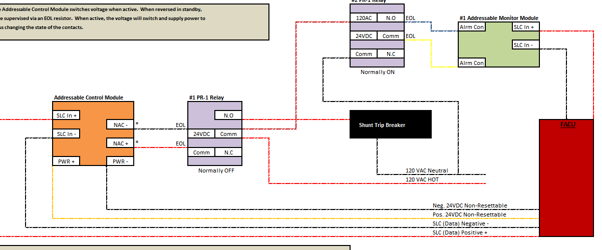
It is important to remember that the wiring between the FACP/FACU and the ECID (Emergency Control Interface Device) needs to be supervised.  In one method below, we are using an addressable relay module (FRM-1) to operate the shunt trip breaker directly.  With this wiring method, only the wire to the FRM-1 (SLC) needs to be supervised.  This is obviously achieved through the SLC and addressing of the device.


In the alternate method, we are showing you how to properly wire up the equipment when the load of the circuit exceeds the rating of the FRM-1.  In this case you would need to install a PR-1 interface relay (rated for 10 amps).  Now that you have a PR-1 switching the shunt trip circuit, this becomes your ECID (Emergency Control Interface Device) and the wiring up to this relay needs to be supervised.  To save the cost of an additional addressable monitor module (FMM-1) we can switch out the FRM-1 with a FCM-1 (addressable control module).  By doing this, we can achieve supervision as well as activation of the PR-1 interface relay through one device.


Elevator Shunt Trip Wiring Diagram


Make sure to download the document and let us know your thoughts.

Strobes Flash When Fire Alarm Silenced

End Users, AHJs (Authority Having Jurisdiction) and Technicians seem to think that fire alarm strobes are required to continue flashing when the fire alarm control unit or panel is silenced.  


Fire Alarm LED Strobe LightsFACT #1:  There is not and never has been anything in the code that requires the fire alarm visual notification appliances AKA Strobes to continue flashing once the fire alarm control panel has been silenced.   

FACT #2:  NFPA 72 2013 Section 10.13.2: “When an occupant notification alarm signal deactivation means is actuated, both audible and visible notification appliances shall be simultaneously deactivated."

So Why did we have Strobes Flashing when the Fire Alarm System has been Silenced?


From what information I have been able to gather, this function crept into the minds of installers and inspectors sometime in the 1980's. The thought of having strobes continue flashing while firefighters validated the alarm condition was a plus.  Firefighters could communicate via their radios without the loud distraction caused by the audible signal.   Lastly, individuals looking to enter a facility would see the visual appliances flashing and know not to enter due to a potential threat of a fire.

This is an argument that comes up less as time moves forward, however, some people are stuck on the ability to have strobes continue flashing during a fire alarm system silence.  Please note that while NOT required by any code or standard, this can still be required within a particular building specification or City Ordinance.

The function can be done by most manufacturers and is not hard to accomplish.  However, it does not make sense to have it enabled and that is why you will not find it in any code references.  Strobes where brought into the code for ADA adaptability.  With that said, does it make sense to leave the strobes flashing if you silence the fire alarm?

Ask yourself, "How is a deaf person affected by this feature?".

When a fire alarm system is activated, a hearing impaired individual will see the strobes flashing but NOT hear the audible tone.  Once the fire alarm panel has been silenced and the audible tone is cut off, this individual has no idea the fire department is on scene, the system as been silenced and the event is being investigated.  To this individual there is still an active evacuation scenario in place until the fire alarm panel has been reset.

Ask yourself, "How is a blind person affected by this feature?".

When a fire alarm system is activated, a visually impaired individual will NOT see the strobes flashing but will hear the audible tone.   If the fire alarm system is silenced and the audible tone is cut off, this individual will have no idea there is still a potential treat in the building.  They could potentially return to their business when in fact there is an active fire alarm investigation occurring in their close proximity.  Another point noted above was the ability for flashing strobes to notify individuals to not enter a building as it is being investigated for a fire.  If you are blind, you would not be aware the fire alarm system is activated and under investigation.  The blind individual could potentially walk right into harmful or fatal situation.  

In my mind this is why NFPA 72 2013 directly addresses this situation in section 10.13.2.  If we agree to just cut off both audible and visual signals in the event of a system silence, we are not favoring or discriminating against anyone with or without a disability.

Join our Facebook Group for up to the minute fire alarm system here.

Have you freshened up on the newer fire alarm LED strobe technology?

Friday, December 16, 2016

NICET Practice Test for Fire Alarm

Why are NICET Practice Tests Only Half the Battle?


It is very important to properly prepare for the NICET Exam.  We recommend not only using NICET Practice Tests but also using other practices such as tabbing your code books, learning the proper way to navigate the references such as NFPA 72 (2013) and NEC or NFPA 70 (2011).  These little practices can cut down on your time thus reducing anxiety as well as giving you time to circle back at the end of your NICET exam to answer any questions you were unsure on.  

What Makes a Good NICET Practice Test?


A good NICET practice test should consist of a wide range of questions as well as the answers with code or standard references.  This helps the user locate the answers in the applicable reference.  Remember that NICET practice tests can only get you so far not only on the actual NICET exam but your future career in the fire alarm industry.  The NICET exam is open book because the industry is always evolving.  NICET understands that learning the applicable codes and how to navigate these references will get you a lot further than forcing you to memorize all of the material.  If you simply memorize the answers to a NICET practice test, you are only cheating yourself.  Solid practice tests for the NICET exam will make it easy to understand where to locate the answers or in some case if the answers are not in a reference, the test should break down the solution in an easy to understand manner.  In short, the NICET practice exams should not only get your ready for your exam, but make you comfortable in using your references on the job. 

You can purchase the Fire Alarms Online NICET Practice Test to the left via the secure PayPal checkout.


NICET FA 1-4 Study Material

NICET Test & Inspect 1-2 Study Material


Fire Alarms Online NICET Practice Test

Please note that the NICET Practice Test questions below are not directly associated with NICET nor are they found on the actual exam.  These questions are taken from our NICET Practice Test as a preview as what you can expect on the exam.

AN INSTALLATION OF A FIRE ALARM SYSTEM THAT SERVES ADJACENT AND NON-ADJACENT PROPERTIES, UNDER ONE OWNERSHIP, IS CONSIDERED A ________________ FIRE ALARM SYSTEM.

A – REMOTE SUPERVISING STATION
B – CENTRAL STATION
C – PROPRIETARY SUPERVISING STATION 
D – AUXILIARY
E – PROTECTED PREMISES

AN INITIATING DEVICE IN WHICH THE SENSING ELEMENT IS DESIGNED TO BE DESTROYED IN THE PROCESS OF OPERATION, IS OF WHAT TYPE?

A – NON-RESTORABLE 
B – SINGLE STATION
C – HEAT DETECTOR
D – LINE
E – SPOT

FPLR STANDS FOR WHICH OF THE FOLLOWING?

A – FIRE PROTECTING LOW RESISTANCE
B – FIRE POWER LIMITED RESISTANCE
C – FIXED POWER LINE RESISTANCE
D – FIRE POWER LIMITED RISER 

MANUAL PULL STATIONS ARE TO BE MOUNTED AT WHAT HEIGHT?

A – 48 INCHES TO THE TOP
B – 48 INCHES TO THE CENTER 
C – 48 INCHES TO THE BOTTOM
D – ANYWHERE WITHIN ARMS REACH

THE TIME DELAY BETWEEN THE ACTIVATION ON AN INITIATING DEVICE AND THE AUTOMATIC ACTIVATION OF A LOCAL FIRE SAFETY FUNCTION, SHALL NOT EXCEED ________ SECONDS.

A – 90
B – 60
C – 30
D – 20
E – 10 

WHILE TESTING A FIRE ALARM SYSTEM YOU REMOVE A TWO WIRE DETECTOR FROM ITS PLUG IN BASE ON A STYLE B TYPE CIRCUIT. WHAT ALARM CAPABILITY WOULD YOU EXPECT FROM THE REMAINING DETECTORS ON THIS CIRCUIT?

A – ANY ACTIVATED DETECTOR WOULD CAUSE AN ALARM
B – ACTIVATED DETECTORS BETWEEN THE CONTROL UNIT AND THE BREAK SHOULD ALARM. 
C – ACTIVATED DETECTORS BETWEEN THE BREAK AND THE EOL DEVICE SHOULD ALARM
D- NONE OF THE REMAINING DETECTORS WOULD CAUSE AN ALARM WHEN ACTIVATED.
E – THE ENTIRE CIRCUIT WOULD BE DISABLED.

PULL STATION SHALL BE WITHIN ________ FEET FROM THE EXIT DOOR.

A – 3
B – 15
C – 5 
D – 3 TO 5
E – 7

WHEN TESTING A WATERFLOW SWITCH, HOW LONG SHALL IT TAKE FOR A SIGNAL TO BE GENERATED AT THE FIRE CONTROL UNIT?

A – WITHIN 90 SECONDS 
B – 1 MINUTE
C – 45 – 120 SECONDS
D – 1 MINUTE TO 2 MINUTES

WHEN RUNNING OPEN WIRE ABOVE THE CEILING, HOW MANY FEET MAX SHOULD EACH STRAP BE PLACED?

A – 2
B – 3
C – 4 
D – 5

WHICH OF THE FOLLOWING IS TRUE WHEN BATTERIES ARE PLACED IN SERIES (FIRE ALARM PANELS)?

A – VOLTAGE DOUBLES AND THE SMALLEST AMP HOUR TAKES PRECEDENCE 
B – VOLTAGE STAYS THE SAME AND THE AMP HOURS ADD UP

SMOKE DETECTORS SHALL BE PLACED NO CLOSER THAN _____ FEET FROM ANY AIR SUPPLY OR RETURN.

A – 3 
B – 10
C – 15
D – IT DOES NOT MATTER

ADDRESSABLE DEVICES ARE ON A ______ STYLE CIRCUIT, CONVENTIONAL INITIATING DEVICES ARE ON A ______ CIRCUIT AND HORN/STROBES ARE ON A _______ CIRCUIT.

A – SLC, IDC, NAC 
B – IDC, SLC, NAC
C – SLC, NAC, IDC
D – IDC, NAC, SLC

HOW MANY FEET FROM THE END OF A CORRIDOR SHALL A HORN/STROBE BE PLACED?

A – 5
B – 10
C – 15 
D – 20
E – 25

HOW MANY FEET FROM THE END OF A CORRIDOR SHALL A SMOKE DETECTOR BE PLACED?

A – 5
B – 13
C – 15
D – 20 
E – 25

OPEN WIRE IS ALLOWED ABOVE THE FINISHED FLOOR AT HOW MANY FEET.

A – 5
B – 7 
C – 9
D – 15

WHAT IS THE MAXIMUM TURNS ALLOWED ON A TAMPER VALVE IN ORDER TO INITIATE A SUPERVISING SIGNAL?

A – 1.5 OR ONE HALF THE TRAVEL OF VALVE
B – 2 OR ONE FIFTH THE TRAVEL OF VALVE
C – 2.5 OR ONE HALF THE TRAVEL OF VALVE
D – 3 OR ONE FIFTH THE TRAVEL OF VALVE
E – 3.5 OR ONE HALF THE TRAVEL OF VALVE

HOW MANY CONDUITS CAN BE CONNECTED TO ONE SEISMIC WIRE?

A – 3 
B – 5
C – 7
D – 10

HEAT DETECTORS SHALL BE PLACED WITHIN _______ FEET OF A SPRINKLER HEAD INSIDE OF AN ELEVATOR SHAFT OR MECAHNICAL ROOM?

A – 2 
B – 4
C – 6
D – 8
E – ALL THE ABOVE

WHAT PAPERWORK IS REQUIRED AT A FIRE ALARM FINAL INSPECTION?

A – APPROVED PLANS AND PERMITS 
B – AS-BUILT
C – NFPA RECORD OF COMPLETION
D – ALL OF THE ABOVE

GIVE A BRIEF DESCRIPTION OF ELEVATOR RECALL. EXAMPLE: A TWO STORY BUILDING. EXPLAIN WHERE SMOKE DETECTORS ARE REQUIRED AND WHAT FUNCTIONS THEY WILL PREFORM.


FIRE ALARM SYSTEMS SHALL HAVE SUFFICIENT BATTERY BACK-UP TO OPERATE THE SYSTEM FOR ______ HOURS OF STAND-BY AND _____ MINUTES OF ALARM.

A – 25/15
B – 5/24
C – 15/60
D – 24/5

EMERGENCY VOICE EVACUATION SYSTEMS SHALL HAVE SUFFICIENT BATTERY BACK-UP TO OPERATE THE SYSTEM FOR ______ HOURS OF STAND-BY AND _____ MINUTES OF ALARM.

A – 24/15
B – 5/24
C – 15/60
D – 24/5

DUCT SMOKE DETECTORS ARE REQUIRED ON HVAC UNITS THAT ARE _______ CFM OR _______ TONS.

A – 2500/7
B – 2000/5
C – 1500/5
D – 1500/6

DUCT SMOKE DETECTORS ARE POWERED UP WITH RESETABLE/NON-RESETABLE POWER. (CIRCLE CORRECT CHOICE) ALSO GIVE A BRIEF DESCRIPTION OF WHY THIS POWER SOURCE IS USED.


CONVENTIONAL DEVICES SUCH AS WATERFLOWS, TAMPER SWITCHES, PULL STATIONS, HEAT DETECTORS AND DUCT DETECTORS USE WHICH CONTACTS?

A – NORMALLY CLOSED
B – NORMALLY OPEN

WHAT IS THE MINIMUM SIZE COPPER WIRE NEEDED FOR A 20 AMP CIRCUIT?

A – 14 AWG
B – 12 AWG
C – 10 AWG
D – 6 AWG

HOW MANY #14 AWG THHN CONDUCTORS CAN BE INSTALLED INSIDE IN A TRADE SIZED 1/2 INCH EMT?

A – 12
B – 10
C – 13
D – 14

HEAT DETECTORS SHALL BE INSTALLED FOR MAXIMUM EXPECTED AMBIENT CEILING TEMPERATURE. THE TEMPERATURE RATING SHALL BE AT LEAST HOW MANY DEGREES ABOVE MAX AMBIENT?

A – 10 F
B – 15 F
C – 20 F

D – PER THE MANUFACTURER’S INSTRUCTIONS AND CLASSIFICATIONS

WHAT IS THE MAXIMUM ALLOWABLE VOLTAGE ON A CLASS 1 CIRCUIT?

A – 24 VOLTS
B – 28 VOLTS
C – 30 VOLTS 
D – 120 VOLTS

WHICH OF THE FOLLOWING CLASSIFICATIONS IS CONSIDERED THE MOST DANGEROUS?

A – CLASS III, DIVISION 1
B – CLASS II, DIVISION 1
C – CLASS III, DIVISION 2
D – CLASS 1, DIVISION 1 

HOW MANY #14 THHN AWG. CONDUCTORS CAN BE INSTALLED IN A ½” TRADE SIZE EMT?

A – 12 
B – 10
C – 13
D – 14

WHAT DOES AN ASTERISK (*) REPRESENT IN NFPA 72?

A – EXPLANATORY INFORMATION FOLLOWS IN THE APPENDIX 
B – AN EXCEPTION TO THE REQUIREMENT FOLLOWS
C – A CHANGE IN INFORMATION FROM LAST CODE EDITION
D – SEE UL STANDARDS FOR DETAILED EXPLANATIONS

EQUIPMENT CONSTRUCTED AND INSTALLED IN CONFORMITY WITH NFPA 72 SHALL BE?

A – APPROVED
B – LISTED 
C – TESTED
D – INSPECTED

WHEN THE WORD “SHALL” IS USED IN NFPA 72 IT WOULD INDICATE A?

A – A MANDATORY REQUIREMENT 
B – A RECOMMENDATION
C – REQUIRED IF DICTATED BY AHJ
D – COMMON INDUSTRY PRACTICE

THE DISCONNECTING MEANS FOR THE FIRE ALARM CIRCUIT SHALL BE?

A – MARKED IN RED
B – ACCESSIBLE ONLY TO THE AHJ
C – MARKED WITH FIRE ALARM CIRCUIT CONTROL
D – BOTH A AND C 

WHEN INSTALLING DETECTORS ON PEAKED CEILINGS, A ROW OF DETECTORS SHALL BE LOCATED?

A – WITHIN 3 FEET OF THE LOW SIDE
B – ON THE SIDE WALL OF THE LOW SIDE
C – WITHIN 1/2 THE LISTED SPACING OF THE PEAK
D – WITHIN 3 FEET OF THE PEAK 

WHEN RUNNING OPEN WIRE ABOVE THE CEILING, HOW MANY FEET MAX SHOULD EACH STRAP BE PLACED?

A – 2
B – 3
C – 4 
D – 5

WHICH OF THE FOLLOWING IS TRUE WHEN BATTERIES ARE PLACED IN SERIES (FIRE ALARM PANELS)?

A – VOLTAGE DOUBLES AND THE SMALLEST AMP HOUR TAKES PRECEDENCE 
B – VOLTAGE STAYS THE SAME AND THE AMP HOURS ADD UP

SMOKE DETECTORS SHALL BE PLACED NO CLOSER THAN _____ FEET FROM ANY AIR SUPPLY OR RETURN.

A – 3 
B – 10
C – 15
D – IT DOES NOT MATTER

SCAFFOLDING AND COMPONENTS SHALL BE CAPABLE OF SUPPORTING A WEIGHT OF?

A – 2X THE MAX INTENDED LOAD
B – 4X THE MAX INTENDED LOAD 
C – MAX INTENDED LOAD PLUS 1000 POUNDS
D – MAX INTENDED LOAD PLUS 1500 POUNDS

HOW MANY FEET FROM THE END OF A CORRIDOR SHALL A HORN/STROBE BE PLACED?

A – 5
B – 10
C – 15 
D – 20
E – 25

HOW MANY FEET FROM THE END OF A CORRIDOR SHALL A SMOKE DETECTOR BE PLACED?

A – 5.5
B – 13.5
C – 15.5
D – 20.5 
E – 25.5

OPEN WIRE IS ALLOWED ABOVE __________ FEET.

A – 5
B – 7 
C – 9
D – 15

WHEN ARE HARD HATS REQUIRED ON JOB SITES?

A – WHEN OSHA STANDARDS ARE ENFORCED
B – FOR GOVERNMENT JOBS
C – ALL CONSTRUCTION SITES
D – WHEN THERE IS A POTENTIAL FOR FALLING OBJECTS 

IN ORDER TO ACHIEVE THE CORRECT LENGTH ON A 90 DEGREE BEND WITH ½” “ CONDUIT ________ INCHES SHALL BE SUBTRACTED FROM THE TOTAL MEASUREMENT.

A – 3
B – 8
C – 5 
D – 6 

HOW MANY CONDUITS CAN BE CONNECTED TO ONE SEISMIC WIRE?

A – 3 
B – 5
C – 7

WHICH TYPE OF DETECTOR IS AFFECTED BY ALTITUDES OVER 3000’?

A – IONIZATION 
B – THERMAL
C – PHOTOELECTRIC
D – PROJECTED BEAM
E – ALL THE ABOVE

LINE TYPE HEAT DETECTORS SHALL BE LOCATED ON THE CEILING OR SIDEWALL NOT MORE THAN ____ INCHES FROM THE CEILING?

A – 10 
B – 12
C – 18
D – 20

A FIRE POWER LIMITED CABLE THAT CAN BE RAN IN PLENUMS IS MARKED AS?

A – FPLR
B – FPR
C – FRLP 
D – FPLP

WHAT DOES NPLFA STAND FOR?

A – NON POWER LIMITED FIRE ALARM
B – NON POWER LIMITED FUSE ATTACHED
C – NON POWER LIMITED FIRE ALARM CIRCUIT 
D – NON PLENUM LIMITED ENERGY FIRE ALARM 

ACCORDING TO NFPA 72 WHEN SHOULD WATERFLOW SWITCHES BE TESTED?

A – ANNUALLY
B – QUARTERLY
C – SEMIANNUALLY 
D – MONTHLY

WHEN INSTALLING LOBBY SMOKE DETECTORS FOR ELEVATOR RECALL WHAT IS THE MAXIMUM DISTANCE THEY MUST BE FROM THE CENTER LINE OF THE ELEVATOR DOOR?

A – 15 FEET
B – 4 FEET
C – 21 FEET 
D – 6 FEET

WHAT IS THE MAXIMUM AMOUNT OF WATERFLOWS ALLOWED TO SHARE AN INITIATING DEVICE CIRCUIT?

A – 2
B – 3
C – 4 
D – 5 

WHAT IS THE MAXIMUM AMOUNT OF SUPERVISORY SWITCHES ALLOWED TO SHARE AN INITIATING DEVICE CIRCUIT?

A – 12
B – 15
C – 20 
D – 25

NOTIFICATION APPLIANCES INTENDED FOR OPERATION IN PUBLIC MODE SHALL HAVE A SOUND LEVEL OF NOT LESS THAN.

A – 55 dBA 
B – 65 dBA
C – 75 Dba 

D – IT DOES NOT MATTER

If you are interested in taking the NICET Test for "fire alarms" or "Inspection and Testing of Fire Alarms", then we have you covered!  We are now selling our CBT Levels 1 - 4 NICET practice test with preparation material.  This material is packed with tons of NICET practice test questions along with all code references as to where to find the answers.  We have also supplied the material with all of the necessary NICET applications, CBT calculator demonstrations, links and more.  If you need more information, feel free to send an email.  You can find the link to purchase our NICET Practice Test on the top left section of this site.

Join our Facebook Group