Showing posts with label Duct Detector. Show all posts

Monday, April 22, 2019

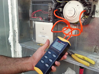
Using a Manometer to Test Duct Smoke Detectors

A Manometer is an electronic device commonly referred to as a liquid column hydro-static instrument.  A Manometer measures pressure and vacuum between the actual duct smoke detector's sample tubes. These manometer units can be used with other manufacturer's duct detectors but for this example we will stick with the System Sensor DNR. 

Manometer Testing Duct Smoke DetectorThe Manometer we chose to use for this article is the Duct Checker manufactured by SDI.  The Duct Checker is light weight, portable and battery operated making it easy to get to areas duct smoke detectors are commonly found. Simply connect the two provided hoses with variable size end plugs and power it on.  Once the unit turns on, press down the "hold" button for three seconds to zero out the machine.  Sort of like a scale.  Now press the "unit" button until you arrive at the selection of "inH2O" on the bottom left of the screen.

The Duct Checker comes with two hoses that are designated for specific ports.  One tube is marked as negative and the other positive.  Make sure to place the hose end of the positive into the actual sample tube inlet.  The negative tube will go into the exhaust port. 

With the System Sensor DNR duct detector you will be looking for a reading of anywhere between 0.01 min and 1.11 max.

Duct Checker Manometer from SDi


With this requirement clearly required in NFPA 72 2016 Table 14.4.3.2 section 17 (g)(5), as well as most manufacturer's documentation, you can expect to come across these at some point in your career.  They are not too pricey so I suggest grabbing one from SDi and placing them in your inspection crew's service vehicles.

Thursday, March 12, 2015

System Sensor D4120 Tamper Troubles

System Sensor D4120 InnovairFlex Duct Smoke Detectors 

These conventional duct smoke detectors include a tamper switch feature that results in a trouble signal at the fire control panel when the duct detector cover has been removed or is not properly installed. If your System Sensor D4120 duct smoke detector is displaying a solid Amber LED, then this is the device's indication that the cover is either missing or not properly tightened down. Keep in mind that this trouble condition will also disable the System Sensor's detector test feature, which is activated using one of the following methods; the Push Button on the power board, the Magnet Test or Remote Test Stations.

System Sensor D4120 Duct Smoke Detector

If you are experiencing this trouble condition, ensure that the System Sensor D4120 duct detector cover of the device is properly aligned and the connecting screws are tightened firmly. When properly attached, a small pole on the cover should contact the bottom left terminal of the tamper switch and depress to contact a terminal on the underside of the cover, closing the tamper switch.

Wednesday, April 23, 2014

Duct Smoke Detectors and Sprinkler Monitoring Systems

Duct Smoke Detectors and Dedicated Function Fire Alarm Systems


Definitions: Building Fire Alarm Systems VS. Dedicated Function Fire Alarm Systems


Building Fire Alarm System: NFPA 72 2022 3.3.118.4.1 = “A protected premises fire alarm system that includes any of the features identified in 23.3.3.1 and that serves the general fire alarm needs of a building or buildings and that provided fire department or occupant notification or both.”


Dedicated Function Fire Alarm System: NFPA 72 2022  3.3.118.4.2 = “A protected premises fire alarm system installed specifically to perform emergency control function(s) where a building fire alarm system is not required.”  NFPA 72 2022 ANNEX A 3.3.118.4.2 = “Examples of a dedicated function fire alarm control unit include an automatic sprinkler alarm and supervisory control unit or an elevator recall and supervisory control unit.”

Building Fire Alarm System: NFPA 72 2022 23.3.3.1 =” Protected Premises fire alarm systems that serve the general fire alarm needs of a building or buildings shall have one or more of the following systems or functions:”

Manual fire alarm signal initiation
Automatic fire alarm and supervisory signal initiation
Monitoring of abnormal conditions in fire suppression systems
Activation of fire suppression systems
Activation of emergency control functions
Activation of fire alarm notification appliances
In-building fire emergency voice/alarm communications
Guard’s tour supervisory service
Process monitoring supervisory systems
Activation of off premises signals
Combination systems

Potter Signal PFC-6006 Sprinkler Monitoring PanelAn example of an application where you shall use a dedicated function fire alarm system is as follows:
An office building with a “B” type occupancy with less than 500 persons throughout or ≤ 100 persons above or below the lowest level of exit discharge.  Based on these factors, a building fire alarm system is not required per the 2021 International Fire Code IFC section 907.  However, per the 2021 International Building Code IBC 903.4 Exception #2, you need to provide monitoring of the sprinkler system if it has ≥ 6 sprinkler heads.  In this case you could install a dedicated function fire alarm system for the monitoring of the onsite sprinkler valves and Waterflow switches.  This dedicated function fire alarm system shall be noted as a “Sprinkler Waterflow and Supervisory System” per NFPA 72 2022 23.8.5.5.1 and 23.8.5.6.1)

NFPA 72 2022 section 23.3.3.2.1 - Dedicated Function Fire Alarm Systems
“In facilities without a building fire alarm system, a dedicated function fire alarm system shall be permitted and shall not be required to include other functions or features of a building fire alarm system.”

NFPA 72 2022 section 23.8.5.4.6.1 Signal Initiation – Duct Smoke Detectors
“Where duct smoke detectors are required to be monitored and a building fire alarm system is installed, a duct detector activation signal shall meet the requirements of 21.7.4”

NFPA 72 2022 section 23.8.5.6.1 Supervisory Signal Initiation – Sprinkler Systems
“Where required by other governing laws, codes or standards to be electronically monitored, supervisory signal initiating devices shall be connected to a dedicated function fire alarm control unit designated as “Sprinkler Waterflow and Supervisory System” and permanently identified on the control unit and on the record drawings.”

“Exception:  Where supervisory signal initiating devices are connected to a building fire alarm system, a dedicated function fire alarm control unit shall not be required.”

What can we take away from this information?


We know that Duct Smoke Detectors (DSDs) when required to be monitored are to be tied into a building fire alarm system per NFPA 72 2022 section 23.8.5.4.6.1.  We also know that a dedicated function fire alarm system is in place to perform a specific function and shall not be required to include additional features of a building fire alarm system. Bottom line is if a building fire alarm system is not installed, duct smoke detectors shall be stand alone and are not required to be connected/monitored by a dedicated function fire alarm system.
Tuesday, October 1, 2013

System Sensor D4120 Duct Detectors Connected the Right Way

If you are involved in the fire alarm industry then chances are you have come across conventional 4-wire duct smoke detectors. Now with new technology, addressable versions of these duct detectors have made connections, wire pulling and programming a lot easier.  Not to mention the cost savings.  In this article, I want to cover the proper method for connecting multiple 4-wire conventional duct smoke detectors on one single IDC (Initiating Device Circuit).  This could be a connection directly off of a conventional loop card or even an addressable monitor module.
Fire Alarm Duct Detector

For reference, we are going to be covering the connections on the System Sensor D4120 model duct detector as this is the most common version used by mechanical contractors.  Also note that the System Sensor D4120 is the replacement for the DH100ACDCLP.  The reason to mentioned this is the fact that System Sensor was smart when creating the newer D4120 by carrying over the same terminal numbers for the connections on the board.  If you were used to connecting to the DH100ACDCLP then you know the alarm contacts were on terminals #4 and #5. Well even though the terminals on the D4120 are not in the same location, they have the same numbers.

When connecting one conventional duct smoke detector, we know that we have to wire the EOL (end of line) resistor in series through the supervisory contacts #3 and #14.  This is a method that is absolutely necessary as it is the only way to properly supervise the detector and IDC.  If the duct detector losses power, has the cover opened, dirty sensor, or a internal wiring problem between the board and the sensor, the supervisory contacts will open thus creating an open circuit and a trouble at the FACP.

Now if we have multiple duct smoke detectors on a single IDC loop, then we need to make sure we wire the EOL resistor in series through all of the detectors on the loop.  This means running an additional pair of wires during the rough in stage.  One pair of wires will be for the IDC (alarm contacts #4 and #5), the second pair will be for the EOL and supervisory contacts (#3 and #4) and the last pair will be for the 24 volts DC resettable power.  Please note that one of the wires on the supervisory pair will run all the way from the last duct detector (terminal #5) on the loop to the first (terminal #14), while the second wire of the pair connects the supervisory contacts of each detector (#3 to #14) on the loop.


If you were to wire the IDC pair through all of the alarm contacts and place the EOL resistor in series through the supervisory contacts on the last duct detector only what would happen?  The answer is, each duct detector would go into alarm, however only the wiring/circuit would be monitored for integrity.  If you do not wire the resistor through each of the detectors supervisory contacts, you are not monitoring the status of the detector itself.  An example would be:  you have three System Sensor D4120 duct detectors on a single loop.  Coming off of your addressable monitor module, you are landing on the alarm contacts of all three detectors.  When you get to the third detector you wire the EOL resistor in series through the supervisory contacts.  Technically the third device is the only detector on the loop that is properly supervised.  If the first duct detector had a loose cover and the second had lost power, you would never know as long as the third device was working properly.  You and the FACP would only know of a trouble on the first two detectors if the third detector had a fault.  This is why it is so important to follow this method.

Key Note***** Make sure to always meter out the supervisory contacts as different duct smoke detector manufacturers label them differently.  Sometimes the contacts reverse when powered up.  In the case of the System Sensor D4120, the resistor is wired through the Common and Normally Open contacts.  Once the unit is powered up and free of any faults, the contacts will reverse and close up and complete the circuit. 

Keep in mind that this method is also required when wiring any other fire alarm device that has separate supervisory or trouble contacts.  The big one to mention is beam detectors.

Make sure to join our Facebook Group HERE

Saturday, May 18, 2013

Duct Smoke Detectors and LED Test Plates

Duct smoke detectors are a common device found in most fire alarm systems from the past and present. Whether the duct smoke detector is addressable or conventional, they both work the same way. A sample tube is inserted into the duct work and samples the air for smoke. If smoke is detected then the photoelectric smoke detector head within the duct smoke detectors sends an alarm signal to the fire alarm panel and shuts down the air conditioning unit.

With that said, most of these duct smoke detectors are located in areas that are not very easily accessed. These areas could include areas such as above t-bar or hard lid ceilings, attic spaces or roof tops. If the actual duct detector is located above a ceiling then access hatches or panels must be provided for obvious reasons. Also if the duct smoke detector is located in an area out of sight then you must provide a detailed description of the device location within the fire alarm control panel program as well as a remote LED plate on the ceiling below the device. This will assist the fire department, end user and technician locate the device. In fact, some jurisdictions such as L.A. County are requiring the remote LED plate to be installed any time you have a duct smoke detector above a ceiling and out of plain view.

With all of this information it is hard for me to understand how some of these local fire alarm installation companies are getting away with installing the remote LED plates on the wall directly above the thermostat controls for the particular HVAC unit. This picture was taken at a local restaurant in the Valencia, CA area. Now with these remote LED plates installed on the wall it makes it easy for fire alarm testing but it totally eliminates their true purpose. If there is a fire reported at the building with a signal coming from a duct smoke detector then the fire department is going to want to know exactly where it's location is the minute they enter. The LED on the wall does not exactly help.

Wednesday, September 15, 2010

System Sensor Duct Detector Applications

System Sensor Duct Detector Applications

NFPA 90A2, “Standard for the Installation of Air Conditioning and Ventilating Systems”, specifies that “Smoke detectors listed for use in air distribution systems shall be located as follows:

(1) Downstream of the air filters and ahead of any branch connections in air supply systems having a capacity greater than 2,000 cfm (944L/sec).

(2) At each story prior to the connection to a common return and prior to any recirculation or fresh air inlet connection in air return systems having a capacity greater than 15,000 cfm (7080 L/sec), and serving more than one story.”

Exception Number One:

“Return system smoke detectors are not required when the entire space served by the air distribution system is protected by a system of area smoke detectors.” (NFPA 90A, 2002, 6.4.2.2)

Exception Number Two:

“Fan units whose sole function is to remove air from inside the building to outside the building.” (NFPA 90A, 2002, 6.4.2.3)

Application Documents

There are several important documents that provide guidance concerning the performance, application and installation of System Sensor duct smoke detectors:

• U.L. Standard 268A, Standard for Smoke Detectors for Duct Applications

• NFPA Standard 90A, Installation of Air Conditioning and Ventilating Systems

• NFPA 92A, Standard for Smoke-Control Systems Utilizing Barriers and Pressure Differences Nfpa 92A: Recommended Practice for Smoke-Control Systems (Gl-92a-88)

• NFPA 92B Standard for Smoke Management Systems in Malls, Atria, and Large Spaces NFPA 92B: Standard for Smoke Management Systems in Malls, Atria and Large Spaces (2009)

• NFPA Standard 72, National Fire Alarm Code

• NFPA Standard 101, Life Safety Code

• ASHRAE Handbook and Product Directory, “Fire and Smoke Control”