Tuesday, October 1, 2013

Is 2 Hour Rated CI Cable Too Much?

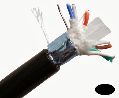
2 hour CI Cable and Survivability

As you may already know, UL (Underwriters Laboratories) has pulled their listing on 2-hour rated circuit integrity (CI) cable.  Since this cable technically no longer exists, what are we to do in current and future installations requiring the use of this CI cable?  According to the UL document, it is now up to the discretion of the local AHJ as to when it can be used or substituted with an alternate means of media.

Now, where did the 2-hour rating come from?  It is my understanding that stairwells are required to be 2-hour rated in buildings over four stories in height.  With buildings that are four stories and under in size, you will typically have a general alarm sequence and won't require any Pathway Survivability.  Buildings over four stories start getting close to the threshold for a high rise building where pathway survivability defiantly plays a role.  Depending on the level of Pathway Survivability (see NFPA 72 2010 section 12.4) level 0, 1, 2, or 3 you will have to protect your circuit pathway for a period of two hours.  Now this can be accomplished by either installing 2-hour rated cable or CI cable, 2-hour rated cable system [electrical circuit protective system(s)], 2-hour rated enclosure or protected area, or 2-hour performance alternatives approved by the authority having jurisdiction (AHJ).  Note that level 0 has no requirement for pathway survivability and level 1 can be accomplished if the building is fully protected by an automatic sprinkler system.

2-Hour Rated CI Cable Fire Alarm

To make it simple, you can run your cables for a fire fighters telephone circuit up a 2-hour rated stairwell without the use of CI cable.  However, when you exit the stairwell to extend the circuit to other areas of the building, you need to use 2-hour rated CI cable.  The intent in my mind is to provide a complete circuit pathway from the fire alarm control unit FACU to the field devices with a rating of not less than 2 hours.

Alright, so the concept is clear, you want to provide a fire alarm system that is capable of lasting at a minimum, 2 hours in the event of a fire.  This allows time for all of the occupants to evacuate and remain clear of the building.  After all it is the ultimate goal of a fire alarm, voice evacuation or mass notification system to notify the occupants of the emergency at hand.  If the wiring fails then obviously you no longer have the ability to broadcast out to your field notification appliances.  Now this is where it gets crazy.  The FACU or Fire Alarm Control Unit is not required to be 2-hour rated nor are the field devices such as fire fighter's telephone jacks, speakers, strobes, horns, etc.  So how is it that we have codes in place to insure that our fire alarm circuit pathways are secure for a period of 2 hours but not the control or notification equipment.  If there is a fire in a high rise that lasts 2 hours, the field devices would not stand a chance.  So what do we have when the fire is all said and done?  A voice evacuation system with operational cables but nothing to activate, control or notify. 

I am not sure as to why UL pulled their listing on CI cable but I honestly am not up in arms about it.  UL is remaining very silent on the issue and will not disclose any information regarding the test results of CI cables.  At this time, to save your customer money and your technicians the hassle  I recommend bringing this topic up with your local AHJ and finding out if he/she will allow the use of other cables in applications requiring NFPA 72 Pathway Survivability Levels 2 or 3.


If you are interested in taking the NICET CBT exam for fire alarms, then we have you covered!  We are now selling our CBT Levels 1 - 3 practice exam DVDs.  These DVDs are packed with tons of NICET CBT practice exams along with all code references as to where to find the answers.  We have also supplied the DVDs with all of the necessary NICET applications, CBT calculator demonstrations, links and more.  If you need more information, feel free to send an email.  You can find the link to purchase our DVDs on the top left section of each page on this site.

Direct Burial Cable for Fire Alarms

Did you know you could direct bury fire alarm cables if codes and standards are followed?


Have you ever used direct burial cable in your fire alarm installations? Typically in fire alarm you will not see much of it as most of our outdoor work is typically in Rigid conduit or schedule 80 PVC.  Also a small portion of our fire alarm designs involve running out side for connections.  Without getting too deep in the design aspects, more than likely, if you are running circuits outside, are likely for a PIV (Post Indicator Valve), or Backflow Preventor with OS&Y switches (OS&Y standards for Outside Screw and Yoke)

Direct Burial Cable for Fire AlarmDirect burial cable is a cable that is designed and U.L. approved to be installed directly in trenches without the need for conduit or other raceways.  The wires themselves are encased with what is known as a thermoplastic sheath that seals out moisture to help protect the wires. Direct burial cable often referred to as UF Cable and commonly ships with a grey jacket. However, there are some wire manufacturers such as Beach Wire and CableArrow Wire and Cable, and Windy City Wire that make their own listed direct burial cable and it comes in black. Please note that this type of cable is only listed for this use if it is installed at the proper depths.

An easy way to notice the difference between standard non-metallic sheathed cable (NM) and underground feeder cable (UF) is the coating around each cable within the jacket. NM cable is simply a jacket to house multiple conductors whereas the UF cable separately coats each conductor.

Why is Copper So Popular in Electronics

Copper Wire for ElectonicsThe electron theory is a good way to explain why copper wire is widely used with electronic equipment and in electrical power distribution. Every substance whether in earth or in space is made up of tiny particles called atoms. These atoms are so small that a piece of copper the size of the head of a needle would contain millions of atoms. Each one of these copper atoms could be considered an actual piece of copper. An atom is not a solid piece of material. The atom itself contains a nucleus in the center which has a positive electrical charge. Traveling around the nucleus in elliptical rings are electrons which have a negative electrical charge. Every electron has the same mass and the same negative charge. There will normally be just enough electrons in the atom to balance the positive charge of the nucleus.


In the diagram below, you will notce that each ring can only contain a certain amount of electrons. The first ring can house 2 electrons, the second ring can hold 8 electrons, the third ring can handle 18 electrons and the fourth ring can hold 32 electrons.

The copper atom's nucleus has a positive charge of 29 in the nucleus. There are typically 29 electrons within the copper atom. With that said, the fourth ring will only house one electron.


When the outer ring of electrons in an atom is filled to the maximum amount possible, that atom will be very stable electronically and chemically. It is almost impossible to remove an electron or to force in an electron.  If the outer ring only has one electron in it, than that electron is not held very closely to the atom and can be easily moved out of its position into space or another atom. This will leave the atom short of one electron to neutralize the positive charge of its nucleus. This will leave the atom with a positive charge.

This is the reason copper wire is so widely used in the electronics industry. It is highly conductive due to its makeup.


If you are interested in taking the NICET CBT exam for fire alarms, then we have you covered!  We are now selling our CBT Levels 1 - 3 practice exam DVDs.  These DVDs are packed with tons of NICET CBT practice exams along with all code references as to where to find the answers.  We have also supplied the DVDs with all of the necessary NICET applications, CBT calculator demonstrations, links and more.  If you need more information, feel free to send an email.  You can find the link to purchase our DVDs on the top left section of each page on this site.


Make sure to join our Fire Alarms Online Facebook Group HERE.

Ground Fault found On PAM Relay Leg


Today I had the pleasure of working on a Saturday. It was a service call to track down and locate a ground fault on a Fire Lite FCPS24 NAC power supply. This ground fault is the reason another company felt it was necessary to disconnect the NAC circuit from the main fire control panel to the NAC circuit power supply. Read about here.
System Sensor PR-1 Relay

We traced out the ground fault on the negative power wire (constant power used for global HVAC shut down) to the rooftop air conditioning units. Upon a close examination of the unit with the ground fault we found that the 120VAC power leg (black) wire on the PAM-1 relay had been pinched in between the 4 S box and cover.

In this case our fire alarm control panel or FCPS24 NAC power supply was powering up the PAM-1 relays. This mean we connected our constant power to the Red (positive) and White (common) wires on the PAM-1 relay. Therefore the black wire is not used. However, the 120VAC lead (black wire) can still transfer a ground fault through the coil.

Always make sure to cap off the black lead and ensure it is not grounded out when using the PAM-1 relay for HVAC shutdown, elevator recall, door holder, etc.

Make sure to join our Fire Alarms Online Facebook Group HERE.

New UL Smoke Alarm Requirements in California

I just attended the monthly CAFAA (California Automatic Fire Alarm Association) meeting and was surprised to find out the new requirements set forth by UL for single and multi-station smoke alarms.  Now these are just for the smoke alarms in household applications.  Not to be confused with system smoke detectors (tied to a building fire alarm system).  The State of California has let a crazy requirement slip through and become adopted for these stand alone household smoke alarms to take effect January 1, 2014.  Get this, the smoke alarms are now required to have the following:
UL Underwriters Laboratories
  1. If the stand alone single station or multi-station smoke alarm is battery operated, the battery has to be sealed in the detector, non-removable, and have a lifetime of 10 years.
  2. The smoke alarm has to be monitored for end of life
  3. The smoke alarm has to have the manufacture date and installation date clearly visible
  4. The smoke alarm must have a Hush feature
Now some manufactures have smoke alarms out there that have some of these features including the Hush feature, 10 year battery and manufacture/installation dates.  Now the tricky one is the monitoring for "End of Life".  The California State Fire Marshall's (CSFM) office reads this as the necessity to provide smoke detectors tied to a building fire alarm system as they can be monitored for dirty sensing elements.  I read it differently.  Manufacturers such as Kidde have detectors with a 10 year battery life.  With that said, the detector will chirp when the battery is at a low level indicating in my mind, "End of Life".  If the detector starts to chirp, it is notifying you that the battery is near dead resulting in the "End of Life" for the smoke alarm detector.

The CSFM has also stated that these requirements are not going to be in affect for wireless battery operated smoke alarms as they report back to a fire alarm system.

Any thoughts on this?

    UL Requires Site Specific 2-Wire Smoke Detector Compatability

    Word on the street is that UL (Underwriters Laboratories) is stating new requirements for the certification in listing compatibility for 2-wire smoke detectors.  If you or your customers have a an FACP (fire alarm control panel) with 2-wire conventional smoke detectors you may be affected by this.

    2-Wire i3 System Sensor Smoke DetectorIf you have the need to replace 2-wire smoke detectors on your existing fire alarm control panel and cannot find UL listed detectors, then you need to know this:   UL is toying with the idea of site specific testing for the certification in listing 2-wire smoke detectors.

    What does this mean for you or your customers?

    Answer:  In the case of an older panel that does not have 2-wire smoke detectors Listed for compatibility, you will have to pay UL to come out to the site and perform their testing.  Now this is not set in stone but it seems pretty crazy to me.  I am not sure of the pricing for this so-called certification process but I know one thing, "It can'y be cheap!".

    At this point, you have to ask your customer or yourself, at what point do you seriously consider upgrading your fire life safety system?  I am reasonably sure the this testing process from UL will impact your customers budget as well as their schedule.

    Like I said, earlier, this is just the word on the street and I cannot verify any of this information.  With that said, it is something to consider and look into if you are currently in this situation.

    CCTV Cameras that Look Like Smoke Detectors are They Allowed?

    Are CCTV Cameras inside of Smoke Detectors Allowed by Code?


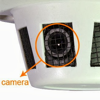
    There are a lot of people that asking me if it is permitted to install look-a-like devices along with an approved fire alarm system.  This is mainly the case with CCTV cameras designed to look like fire alarm system smoke detectors of smoke alarms.  Now to the trained eye of a seasoned technician, it is always easy to spot these devices as they do not look like any of the system smoke detector or smoke alarm brands we have grown accustom to.

    Customers like these CCTV Smoke Detector devices because it gives them the sense of security without having to display an obvious CCTV camera.  Most of the time, I feel that these are used in the situation where an owner wants to keep an eye on his or her employees.   If the  CCTV camera is hidden inside of a smoke detector, then the employees would be unaware they are being filmed and may be caught performing unlawful acts and then fired.  In the case of preventing robbery I believe you should have an obvious CCTV camera in plain sight.  This will act as a deterrent and possibly prevent any acts of theft in the first place.

    Smoke Detector with CCTV CameraNow on to the question at hand.  Are these Smoke Detector Cameras permitted to be installed along side an approved fire alarm system?  Some people say no as they provide a false sense of security in the event of a fire emergency while others say it is just fine as it is not tied to or part of the system.

    The International Fire Code 2015 (IFC) section 901.4.5 - Appearance of Equipment.  "Any device that has the physical appearance of a life safety or fire protection equipment that does not perform that life safety or fire protection function, shall be prohibited."

    Now this is like anything else.  Always check with your local AHJ.  Typically these discrete Smoke Detector CCTV cameras will be installed after the initial fire alarm inspection and won't be seen by the AHJ.  If you notice one of these discrete smoke detector camera during a semi or annual fire alarm device test, note it down and discuss with the local AHJ.  I believe that if everyone is on the same page and you have it well documented in your Fire Alarm Inspection and Testing paperwork, then you are covered.


    If you are interested in taking the NICET Test for "fire alarms" or "Inspection and Testing of Fire Alarms", then we have you covered!  We are now selling our CBT Levels 1 - 4 NICET practice test with preparation material.  This material is packed with tons of NICET practice test questions along with all code references as to where to find the answers.  We have also supplied the material with all of the necessary NICET applications, CBT calculator demonstrations, links and more.  If you need more information, feel free to send an email.  You can find the link to purchase our NICET Practice Test on the top left section of this site.

    UUKL Smoke Control For Fire Alarms

    UUKL Smoke Control PanelUL (Underwriters Laboratories) has a section titled 864.  ANSI/UL-864 is the section that covers "Standards for Control Units and Accessories for Fire Alarms".  ANSI/UL 864 is currently on its 9th revision.  Published on September 30, 2003 with a current effective date of December 31, 2008, the new edition incorporates approximately 300 changes, including 100 pages of new requirements from the previous edition.


    With that said, UUKL is a separate listing category under UL 864.  Control devices used in smoke control systems have a UUKL listing.  UL's UUKL listing is a category under UL 864, Control Units and Accessories for Fire Alarm Systems.  UUKL is for products covered under the description "Smoke Control Equipment."  Equipment that receives UL's UUKL rating has been tested for integrity and long term reliability.  The equipment is subjected to extreme temperatures, humidity  and electrical transients and surges. This testing ensures that the devices will continuously perform even under severe and abnormal conditions.

    A UUKL Smoke Control System is a combination of fan, dampers, warning devices, relays and modules that all work together to perform the containment function of any smoke event at any location in a building.  If the UUKL Smoke Control System is design correctly it should inhibit and or prevent the movement of smoke into areas leading to exits or other areas designated safe zones in a building.

    Read more about UUKL Smoke Control Panels HERE.


    make sure to join our Facebook Group for great discussions HERE!!!!

    Water Flow, Backflow, OSY, Tamper Switch

    Wet system (fire sprinkler lines) is constantly filled with water as opposed to a dry system such as a pre-action system (we will talk about these later). The water in the sprinkler line is monitored by a pressure gauge usually located near the main fire riser and waterflow switch.

    Also you will find a tamper switch located in strategic places as to separate the system into different sections as needed for maintenance and or emergencies. These will be typically located on each level of a facility. There are sure to be additional locations but it stickily depends on the layout of the facility and sprinkler system.
    Fire Sprinkler Backflow OS&Y
    Another key item to point out in wet system installations is the Backflow Preventer also known as an OS&Y (outside screw and yoke). This contraption reduces the city back pressure from causing a false alarm signal at the water flow device.

    To make things simple for this post we will assume we have a water flow switch on each floor off the facility. The water flow device is mounted onto the main portion of the riser before any sprinkler heads. Attached to the water flow switch is a large flapper that is inserted into the riser pipe. Once the system is filled with water and is holding pressure, the water flow paddle holds firm.

    How it all works:

    Once a sprinkler head reaches its destruction point it pops and opens up the valve attached the the fire sprinkler system. Now that the stored water has a place to escape it pours out with extreme pressure to suppress the fire. While this water is pouring out, it needs to be replaced. With the water pressure coming into the sprinkler system the water is replaced one for one. Once this cycle starts, the flapper behind the water flow switch is activated just like a light switch. As required by NFPA 72 the Water Flow switch shall initiate an alarm within 90 seconds. This adjustment can be achieved by tuning a small dial on the water flow device itself. In case you are wondering, the 90 second delay is to help prevent nuisance alarms from leaks, water surges, city back pressure, etc.  Also located on the water flow switch is two sets of dry contacts. One of these sets will be used for the 120VAC switch leg to the sprinkler bell and the other is to be used for the connection to the fire alarm control panel for the purpose of alerting the occupants and central station dispatch.  This is a very simple explanation of how a wet fire sprinkler system works. Let me know if you would like more details.  It is also nice to note that the movies always have it wrong. They seem to think that if one sprinkler head bursts that they all go. Nothing could be further from the truth.

    Make sure to join our Fire Alarms Online Facebook Group HERE.

    System Sensor D4120 Duct Detectors Connected the Right Way

    If you are involved in the fire alarm industry then chances are you have come across conventional 4-wire duct smoke detectors. Now with new technology, addressable versions of these duct detectors have made connections, wire pulling and programming a lot easier.  Not to mention the cost savings.  In this article, I want to cover the proper method for connecting multiple 4-wire conventional duct smoke detectors on one single IDC (Initiating Device Circuit).  This could be a connection directly off of a conventional loop card or even an addressable monitor module.
    Fire Alarm Duct Detector

    For reference, we are going to be covering the connections on the System Sensor D4120 model duct detector as this is the most common version used by mechanical contractors.  Also note that the System Sensor D4120 is the replacement for the DH100ACDCLP.  The reason to mentioned this is the fact that System Sensor was smart when creating the newer D4120 by carrying over the same terminal numbers for the connections on the board.  If you were used to connecting to the DH100ACDCLP then you know the alarm contacts were on terminals #4 and #5. Well even though the terminals on the D4120 are not in the same location, they have the same numbers.

    When connecting one conventional duct smoke detector, we know that we have to wire the EOL (end of line) resistor in series through the supervisory contacts #3 and #14.  This is a method that is absolutely necessary as it is the only way to properly supervise the detector and IDC.  If the duct detector losses power, has the cover opened, dirty sensor, or a internal wiring problem between the board and the sensor, the supervisory contacts will open thus creating an open circuit and a trouble at the FACP.

    Now if we have multiple duct smoke detectors on a single IDC loop, then we need to make sure we wire the EOL resistor in series through all of the detectors on the loop.  This means running an additional pair of wires during the rough in stage.  One pair of wires will be for the IDC (alarm contacts #4 and #5), the second pair will be for the EOL and supervisory contacts (#3 and #4) and the last pair will be for the 24 volts DC resettable power.  Please note that one of the wires on the supervisory pair will run all the way from the last duct detector (terminal #5) on the loop to the first (terminal #14), while the second wire of the pair connects the supervisory contacts of each detector (#3 to #14) on the loop.


    If you were to wire the IDC pair through all of the alarm contacts and place the EOL resistor in series through the supervisory contacts on the last duct detector only what would happen?  The answer is, each duct detector would go into alarm, however only the wiring/circuit would be monitored for integrity.  If you do not wire the resistor through each of the detectors supervisory contacts, you are not monitoring the status of the detector itself.  An example would be:  you have three System Sensor D4120 duct detectors on a single loop.  Coming off of your addressable monitor module, you are landing on the alarm contacts of all three detectors.  When you get to the third detector you wire the EOL resistor in series through the supervisory contacts.  Technically the third device is the only detector on the loop that is properly supervised.  If the first duct detector had a loose cover and the second had lost power, you would never know as long as the third device was working properly.  You and the FACP would only know of a trouble on the first two detectors if the third detector had a fault.  This is why it is so important to follow this method.

    Key Note***** Make sure to always meter out the supervisory contacts as different duct smoke detector manufacturers label them differently.  Sometimes the contacts reverse when powered up.  In the case of the System Sensor D4120, the resistor is wired through the Common and Normally Open contacts.  Once the unit is powered up and free of any faults, the contacts will reverse and close up and complete the circuit. 

    Keep in mind that this method is also required when wiring any other fire alarm device that has separate supervisory or trouble contacts.  The big one to mention is beam detectors.

    Make sure to join our Facebook Group HERE

    Notifier FirstVision Touchscreen Annunciator

    Notifier FirstVision

    Notifier ONYX Series FirstVision

    For a while now, Notifier has had a beautiful touchscreen fire alarm annunciator titled ONYX FirstVisionFirstVision annunciator they will be able to quickly and accurately locate the device(s) in alarm.  With that said, the programmer and system installer can also distinguish valuable information right on the First Vision screen.  Information such as what types of potential hazards are located in the rooms.  Is there paint, gas, chemicals?  Before it was almost impossible to know.  Notifier has now outdone themselves once again with this beautiful and effective FirstVision fire alarm annunciator.  Two other nice features are the two USB jumpers from the Notifier FirstVision to the cabinet.  This makes it nice for programming.  The other is the automatic locking solenoid for the enclosure door.  If there is a fire alarm condition, the Notifier FirstVision door will automatically unlock itself so that the fire department or first responders can easily go to work.

    This annunciator boasts a 19" LCD display which not only shows the system condition, but the actual floor plans of the facility and the location of each device.  On top of the fire alarm devices, you can also display the location of items such as: roof access, gas shut off, locked doors, areas of refuge, HVAC shut off, etc.  This tool is unbelievably valuable to the first responders as it drastically reduces research time.  When the fire department responds to a fire in a facility with a Notifier ONYX series fire alarm system.


    Here is some info to help you understand it size and current listings.

    Cabinet Size:  24.63" W x 22.03" H x 3.47" D
    Door Dimensions:  26" W x 22.75" H x 1.016 cm D
    Power Requirements:  24VDC @ 3.0 amps, Regulated, filtered and non-resettable
    UL/ULC Listed #S5697
    MEA: 286-07-E
    CSFM: 7300-1525:0103
    FDNY: COA#6070

    If you would like additional information on the ONYX First Vision touchscreen annunciator, contact Pyro-Comm Systems, Inc.  They are a NESCO affiliate for Notifier with extremely knowledgeable staff to answer your questions.

    Make sure to join our Fire Alarms Online Facebook Group HERE.

    Wednesday, June 19, 2013

    Carbon Monoxide Detector Mounting

    Carbon monoxide alarms and detection systems now have more direction on mounting and alerting thanks to NFPA 72 2022


    NFPA 720: Standard for the Installation of Carbon Monoxide (CO) Detection and Warning Equipment (2015) currently does not have any requirements for the mounting height/location of a carbon monoxide detector.  However, NFPA 720 does specify that is a carbon monoxide detector is installed in a room with a fire fueled appliance such as a generator, hot water heater, furnace, etc., it is to be mounted on the ceiling.

    The reason behind the NFPA 720 placement of carbon monoxide detectors on the ceiling in these areas is makes perfect sense. Continue below:  

    Carbon Monoxide Poisoning with Fire Alarms

    Carbon monoxide has a molar mass of 28.0, which makes it slightly lighter than air, whose average molar mass is 28.8. According to the ideal gas law, CO is therefore less dense than air.  With that said, the heat generated by these appliances will make the carbon monoxide (CO) more buoyant and present it to the carbon monoxide detector on the ceiling.

    Another source for the mounting and installation of carbon monoxide detectors is found in NFPA 72 2019 section 17.12 "Carbon Monoxide Detectors"

    NFPA 72 Carbon Monoxide Requirements per Chapter 17

    NFPA 72 2022 Section 17.12.1 
    Where required by other governing laws, codes, or standards, carbon monoxide defectors shall be installed in accordance with the following:
        1) On the ceiling in the same room as permanently installed fuel-burning appliances, and

        2) Centrally located on every habitable level and in every HVAC zone of the building, and

        3) Outside of each separate dwelling unit, guest rom, and guest suite sleeping area within 21 feet (6.4 m) of any door to a sleeping room, with the distance measured along the path of trave, and

        4) Other locations where required by appliance laws, codes, or standards or
        
    NFPA 72 2022 Section 12.12.2 
    Carbon monoxide detectors shall meet the following requirements:
        1) Carbon monoxide detectors shall be listed in accordance with applicable standards, such as ANSI/UL 2075, Gas and Vapor Detectors and Sensors.

        2) Carbon monoxide detectors shall be set to respond to the sensitivity limits specified in ANSI/UL 2034, Standard for Single and Multiple Stations Carbon Monoxide Alarms.

    NFPA 72 2022 Section 17.12.4 
    All carbon monoxide detectors shall be located and mounted so that accidental operation will not be caused by jarring or vibration. 

    NFPA 72 2022 Section 17.12.5 
    The location of carbon monoxide detectors shall be based on an evaluation of potential ambient sources and flows of carbon monoxide, moisture, temperature, dust, or fumes and of electrical or mechanical influences to minimize nuisance alarms. 

    NFPA 72 Carbon Monoxide Requirements per Chapter 18

    NFPA 72 2022 Section 18.4.3.1 
    Where a carbon monoxide detector or alarm is required by other codes or standards or by the authority having jurisdiction and where an audible signal is required, a distinctive signal patter shall be required that is different from a fire evacuation signal.

    We know this as Temporal Code 4

    NFPA 72 2022 Section 18.4.3.2 
    Where an audible signal is required, the carbon monoxide signal shall be four-pulse temporal pattern and comply with the following:
        1) Signals shall be a pattern consisting of four cycles of 100 milliseconds +/- 10 percent "on" and 100 milliseconds +/- percent "off" followed by 5 seconds +/- 10 percent "off" as demonstrated in figure 18.4.3.2

        2) After the initial 4 minutes of the carbon monoxide signal, the 5-second "off" time shall be permitted to be changed to 60 seconds +/- 10 percent.

        3) The alarm signal shall be repeated in compliance with 18.4.3.2(1) and 18.4.3.2 (2) until the alarm resets or the alarm signal is manually silenced.


    temporal code 4 figure


    NFPA 72 2022 Section 18.4.3.3
    The signal shall be synchronized within a notification zone of a protected premises. 

    NFPA 72 2019 Section 18.4.3.4 
    The audible signal of carbon monoxide alarms and systems installed to meet the requirements of NFPA 72 chapter 29 shall NOT be required to be synchronized.

    NFPA 72 2022 Section 23.8.4.9
    Unless otherwise permitted by 23.8.4.9.1 signals form carbon monoxide detectors and carbon monoxide detection systems transmitted to a fire alarm system shall be indicated as a carbon monoxide alarm signal. No more general supervisory signals for carbon monoxide alarms or detection system. 

    NFPA 72 2022 Section 23.8.6.1.2
    Except as permitted in 23.8.61.3 occupant notification of carbon monoxide systems shall be throughout the protected premises. 

    NFPA 72 2022 Section 23,8.6.1.3
    Where carbon monoxide alarm signals are transmitted to a constantly attended on-site location or off-premises location in accordance with this chapter, selective public mode occupant notification zone encompassing the area where the carbon monoxide alarm signal was initiated. 

    NFPA 72 2022 Section 23.8.6.3.3
    The boundaries of carbon monoxide alarm notification zones shall be coincident with the area where the alarm initiation originated and other signaling zones in accordance with the building's emergency response plan. 

    On another note, make sure that when you place your carbon monoxide detector outside of the sleeping area you still achieve a sound level of 75dB at the pillow with the door closed.

    Read more hear about the new laws and state legislation for carbon monoxide detection in California.


    Make sure to join our Fire Alarms Online Facebook Group HERE.

    Drywall Dust Problems with System Sensor Smoke Detector

    If any packaged air conditioning units are run during the drywall installation phase of building construction to assist in the drying of joint compound, the fine dust created by sanding of those drywall joints may compromise the System Sensor smoke detector sensor heads within the duct housing. The 2D51 System Sensor Head in the InnovairFlex Duct Smoke Detector models D4120, D4120W and D4S may display a “maintenance” condition that will require replacement or cleaning of the sensing chambers on the smoke detector head. The “maintenance” condition will be indicated on the fire alarm control panel, on the sensor itself or power board of the duct smoke detector (the sensor LED will blink “red” every five seconds and the power board LED will blink “amber” every five seconds).

    To avoid this condition, it is recommended that the System Sensor smoke detector heads be removed during the construction phase and replaced once construction is completed and the Certificate of Occupancy is issued. The sensor heads twist out for removal and twist in for insertion.

    Below is an extracted image of the System Sensor duct smoke detector sensor head:


    Cleaning the sensing chamber on the sensor head

    If the System Sensor smoke detector heads are not removed during the construction phase and the sensor chamber becomes dirty causing a maintenance condition (it will not always be visible on the exterior black screen on the sensor head), the sensor head must be cleaned with compressed air. To clean the sensor head chamber, follow these step-by-step instructions see the video demonstration below:

    1. Remove the System Sensor smoke detector head to be cleaned from the duct smoke detector housing by twisting it in a counterclockwise direction.
    2. Remove the smoke sensor cover by pulling outward on each of the four removal tabs that hold the cover in place.
    3. Vacuum the screen carefully without removing it. If further cleaning is required continue with Step 4. Otherwise, skip to Step 7.
    4. Remove the chamber cover/screen assembly by pulling it straight out.
    5. Use a vacuum cleaner or compressed air to remove dust and debris from the sensing chamber.
    6. Reinstall the chamber cover/screen assembly by sliding the edge over the sensing chamber. Turn until it is firmly in place.
    7. Replace the cover using the holes for the LEDs for alignment and then gently push it until it locks into place.
    8. Reinstall the System Sensor smoke detector head in the duct smoke detector housing by aligning it in the housing and twisting it in a clockwise direction.

    Note: Cleaning only the sensor head’s exterior black screen will not remove any drywall dust in the smoke sensing chamber.
    Note: Should the System Sensor duct smoke detector remain in a “maintenance” condition after cleaning, then it may require the complete replacement of the sensor head. The replacement sensor head is model 2D51.


    It is Illegal to Tamper with Fire Alarm Systems

    Today I rode along with some of our technicians to perform an annual fire alarm inspection of a three story apartment complex with approximately 140 units. The system comprised of a Gamewell IF610-252 addressable fire alarm control panel with Wheelock notification devices. On the first floor there were 20 handicap units with addressable system smoke detectors (Apollo XP95-P) which activated a signal module for the notification appliance circuit within its designated unit.

    Now, the addressable system smoke detectors in the handicap units were programmed to supervisory events for the purpose of central station monitoring and common area notification of the facility. However, the individual notification devices within the unit were supposed to activate if the photoelectric smoke detector was activated. Needless to say, this system was messed up. Some of the smoke detectors failed to activate the NACs and other actually activated the common corridor devices. We also found that the installing fire alarm company did not design the system with SYNC modules.

    How this facility passed it original acceptance test is beyond me.

    Tampering with Fire Alarms is illegal

    On top of all of this we came across 4 units where the occupant had tampered with the fire alarm system mini horn within their living room. We had to remove the tape, cotton, plastic and whatever else they could find to suppress the sound from the devices and warn the occupants that it is a crime to tamper with fire alarm equipment. For your reference, the California Penal Code section for this is 148.4

    It reads:

    a) Any person who does any of the following is guilty of a misdemeanor and upon conviction is punishable by imprisonment in a
    county jail, not exceeding one year, or by a fine, not exceeding one thousand dollars ($1,000), or by both that fine and imprisonment:

    (1) Willfully and maliciously tampers with, molests, injures, or breaks any fire protection equipment, fire protection installation,
    fire alarm apparatus, wire, or signal.

    (2) Willfully and maliciously sends, gives, transmits, or sounds any false alarm of fire, by means of any fire alarm system or signal
    or by any other means or methods.

    (b) Any person who willfully and maliciously sends, gives, transmits, or sounds any false alarm of fire, by means of any fire
    alarm system or signal, or by any other means or methods, is guilty of a felony and upon conviction is punishable by imprisonment in the state prison or by a fine of not less than five hundred dollars ($500) nor more than ten thousand dollars ($10,000), or by both that fine and imprisonment, if any person sustains as a result thereof, any of the following:

    (1) Great bodily injury.

    (2) Death.


    If you are interested in taking the NICET CBT exam for fire alarms, then we have you covered!  We are now selling our CBT Levels 1 - 3 practice exam DVDs.  These DVDs are packed with tons of NICET CBT practice exams along with all code references as to where to find the answers.  We have also supplied the DVDs with all of the necessary NICET applications, CBT calculator demonstrations, links and more.  If you need more information, feel free to send an email.  You can find the link to purchase our DVDs on the top left section of each page on this site.

    Make sure to join our Fire Alarms Online Facebook Group HERE.

    SLC Circuit for Duct Detectors Done the Easy Way

    Okay we are back to the amazing installation practices that some fire alarm and security companies will perform to lower their labor time and land the job. However, after you will see in this amazing video you will wonder how some of these companies get away with it. And if they are doing these installs after the acceptance test, then how are they living with themselves? Better yet, how does the customer not make themselves aware of what they are paying for? Words cannot express the frustration that myself and other competent contractors feel when they see installs like this.

    Here is what we have for you today. This video shows a quick clip of some conventional System Sensor duct smoke detectors installed within the rooftop HVAC unit. However, the previous fire alarm contractor thought it would be a good idea to run a standard 18 awg (American wire gauge) 2 conductor PVC cable open wire across the rooftop from unit to unit. They drilled a hole in the side of each HVAC roof top unit and proceeded to run this PVC cable across the roof and tied them directly to the addressable module for each System Sensor duct smoke detector. This was obviously done because the contractor was one of two things: 1 he was to lazy to get a scissor lift below the deck and find the problem, or 2 he was just not competent enough to resolve the issue without pulling off this nightmare. You be the judge!


    Friday, June 14, 2013

    Gamewell IF610 vs. Lightning. Got Surge Protection?

    We just pulled out a Gamewell IF610-504 at a military base in California. Now they claim that lightning is the cause of the damage and from the looks of the board I could definitely agree. The fuse located directly to the left of the incoming 24VDC from the transformer was not blown which is a good indication that the surge was extremely powerful and quick. This power surge blew out the main board, the CPU, the display and the 4 SLC loop card even though the only visible damage was on the main board. It appears that the power surge was so powerful that it burned a hole through the Gamewell IF610 board. This is why it is so important to have Transient Surge Protection for your fire alarm systems.

    Unfortunately for our customer these boards are not readily available from the Gamewell factory so the down time is about two weeks.Check out these pictures.


    Gamewell IF610 FACP Board Hit by Lightning
    Gamewell IF610 FACP Board Hit by Lightning


    Sunday, May 19, 2013

    Card Access System Layout

    TOP 10 Card Access Sales Questions

    When you visit a job site to gather information for a card access quote, consider these questions:


    1) How many doors need Card Access Control?

    2) How many users will the Access Control system require?

    3) How many locations/zones/partitions need Card Access?

    4) Are there any existing Card Access readers?

    5) If so what is the current card access system being used?

    6) Do they have a card access reader and/or credential preference?

    7) Do they want to integrate any other security with the Access Control?

    I.E. Intrusion panel or Video?

    8) Do they have an existing video platform?

    9) Is there existing platform IP or Analog?

    10) How old is the video system?

    Once you have completed these questions, you will find that designing your card access system will be much easier.  Also ask the client if they have a scale drawing of the floor plans that you can acquire before your job walk.  This gives you a good starting point and area to make detailed notes.

    Pre Alarm Fault on Gamewell 600 Series FACP


    Have you ever replaced an Apollo XP95-P or XP95-I addressable smoke detector on a Gamewell 600
    series fire alarm control panel? If you have been in the industry for a while, then chances are that you have.

    Gamewell Apollo detector head XP-95TLet me paint a scenario for you. You receive a call from a customer or your central station claiming that their Gamewell 600 series fire alarm control panel is displaying a missing fault for an addressable smoke detector. Your technician responds and replaces the device one for one. (of course this is after he or she troubleshoots the other probable causes for a missing device) Now if you have determined that the device was bad and needed to be replaced then there should be no issues with a one for one swap, "right?'. Well the anser is yes and no. Most of the time the panel will poll the SLC (signaling line circuit) loop and find the newly installed XP95-P or XP95-I. On some occasions the fire alarm control panel may display a Pre-Alarm condition for that brand new device.

    According to Gamewell's technical support department, this is caused from the panel's internal memory for each device's status. So theoretically the fire control panel is still finding the status of the old device for that particular address. Maybe before the device went missing it was dirty to the point of no return. Now the panel is showing a Pre-Alarm due to the mistaken identity of the old vs. new device.

    With that said, have no fear there is a quick fix. Simply enter programming mode through the front display and select #1 for "Circuit Programming" then select #3 for "Initialize Circuit". Once the panel finishes scrolling through a few items enter the circuit number that the particular device is on and hit enter. This should re-poll the entire loop and reset the panel's memory for that device. To exit programming mode continue to hit the "enter" key until the panel displays "Commencing System Reset".

    This should take care of your fault. If not read my article on Gamewell's 600 Series Soft Reset.

    NICET Level 4 Major Project Writeup


    If you need your NICET certification in "Fire Alarm Systems", then you have found the right place. Our site contains a ton of great information to help you achieve any NICET certification. If you are pursuing your NICET Level 4 certification you will need to perform what NICET refers to as a Major Project Write up.

    The NICET certification level 4 Major Project Write up consist of a two to three page concise and detailed description of one major fire alarm system project.  Simply put you will need to write about a sophisticated fire alarm system you were involved with from design to final inspection. Here are a few things to keep in mind when drafting up your essay:

    1 - Give a good description of the project and how your were involved.
    2 - The NICET Certification level 4 Major Project Write up must be a separate document from your work history.
    3 - The fire alarm project you choose to discuss must be within the past 3-4 years.
    4 - Be sure to include all of your responsibilities, job duties and practices used to accomplish the completion of the project.


    We have complied a digital download to assist fire alarm technicians with practicing for the NICET certification exam. Our material also contains Major Project Write up guidelines and another documentation on how to properly write an essay. All of this drastically helps as this process can be very tedious.


    With NICET continuing to strive in their efforts to properly certify technicians in the field of fire alarm, it is important to stay up to date with their regulations and requirements. Visit NICET for more information or check out our material for NICET practice tests and NICET study material.

    Wow System Sensor D4120 Duct Detector is Now Fixed

    System Sensor D4120 DNR Duct Smoke DetectorA while back I posted on the new System Sensor D4120 duct smoke detector. I stated that although a great improvement on the previous DH100 series it did have one major flaw. The System Sensor D4120 duct smoke detector would open the supervisory contact when powered up causing a trouble condition at the main fire control panel every time the end user or tech performed a reset. This was a major deal especially when you have a new high rise with over 60 of these new System Sensor D4120 duct detectors. The AHJ (authority having jurisdiction) typically does not understand why the fire control panel starts receiving 60 troubles when you reset the system.
    Our tech department has been contacting System Sensor for months (ever since this device came out) trying to get an answer as to why they did this.

    Well I am happy to report that System Sensor finally listened and has corrected the issue. Now when power is restored to the D4120 the supervisory contact will close immediately. Great job System Sensor with what we can now call another awesome product.

    Read more from System Sensor here.

    NICET Certification with New CBT Format

    Has anyone taking the NICET certification exam with the new CBT (Computer Based Testing) format? I am under the impression that it is the same exam (questions and NICET elements). I completed my NICET level IV before the CBT went into effect.

    I know that the Sate exams such as the California State fire technician certification exam is based on a multiple choice format through computer. It defiantly makes things nice not having to bubble in all of your answers on a scan-tron with a #2 pencil.

    I would appreciate any help and or feedback on the new NICET testing procedures as I need to update my NICET fire alarm training CD. I am pretty sure it wont matter as the NICET questions are most likely the same.

    Also can you still challenge questions on the new NICET test format?

    If you are interested in taking the NICET Test for "fire alarms" or "Inspection and Testing of Fire Alarms", then we have you covered!  We are now selling our CBT Levels 1 - 4 NICET practice test with preparation material.  This material is packed with tons of NICET practice test questions along with all code references as to where to find the answers.  We have also supplied the material with all of the necessary NICET applications, CBT calculator demonstrations, links and more.  If you need more information, feel free to send an email.  You can find the link to purchase our NICET Practice Test on the top left section of this site.

    Make sure to join our Fire Alarms Online Facebook Group HERE.

    Another thing I heard is it takes a lot less time to receive your results. Maybe instant.

    Fire Alarm Speaker Amplifiers New vs. Old

    Old Analog FCI Fire Alarm Voice EVAC speaker amplifierWow times have changed. Check out these two pictures. The first one is a cabinet full of old fire alarm speaker amplifiers found at a high rise we are currently working at. CHeck out the size that each one of these take up.
    Its amazing to think that back in the day this was state of the art!

    Like I mentioned earlier, we are changing this existing system out one floor at a time so we currently have our FCI E3 voice system side by side with the old fire alarm panel in the electric room. This is where you truly notice the difference in modern technology. Check out this next picture of the FCI E3 AM-50 cards. New FCI E3 AM-50 Fire Alarm Voice RVAC speaker amplifiersThere are four installed in this one picture, each with the capability of two supervised fire alarm speaker circuits with 50 watts.

    It can't wait to see what the next 40 years will bring us.

    I have also included some random pictures of this install to show how we have temporarily mounted the new FCI E3 fire alarm control panel using uni-strut. Once the entire high rise building has been switched over to the new FCI E3 we will demo out the old panel and move our new system to the wall.

    Make sure to join our Fire Alarms Online Facebook Group HERE.


    PSI technician with FCI E3 fire alarm panel
    FCI E3 NGA Touchscreen Keypad on temp mounted FCI E3 FACP


    When Are Fire Alarm Batteries Required to be Replaced

    What is the Code for Replacing Fire Alarm Batteries?


    It is common knowledge in the fire alarm installation industry that fire alarm batteries are to be replaced typically within 4-5 years from date of manufacturing. What you will commonly notice with companies is a lack of experience resulting in dead fire alarm batteries. Most fire alarm technicians will simply take a label maker or Sharpie and write down the installation date on the backup fire alarm batteries.

    You may ask yourself, "What's wrong with this?"

    Fire Alarm Battery Manufacturer Date Code

    The answer is simple. As stated above the the fire alarm batteries must be replaced with 4 - 5 years from date of manufacture. If you write the installation date on the batteries then you are not noting accurate information. The reason for this is that there is no telling how long those fire alarm batteries sat in your warehouse or even the manufacturer's warehouse.

    What's the Correct Way to Note the Battery Date?


    Fire Alarm Back-up battery manufacturers are stamping the fire alarm batteries with the month and year of manufacture. This is the date that you want to mark down.  The fire alarm battery pictured above is manufactured by Power Sonic and has a date tamp of 10194-H on it.  I wont go into too many details about battery date codes as I have another files to assist you with this.  The code of 10194 = the Month (10) the Day (19) and the Year (2004). So as you can see by a technician labeling the batteries new on "2/2/2015" throws things off a bit.  If you want to download our multi-tool with voltage drop calculations, battery calcs, dB loss and battery date codes, click here.

    For your reference I have included the NFPA 72 2013 edition code sections below:

    Table 14.4.3.2 #9  Fire alarm batteries shall be replaced in accordance with the recommendations of the alarm equipment manufacturer or when the recharged battery voltage or current falls below the manufacturer's recommendations.

    10.6.10.1.1 When the fire alarm batteries are not marked with the month/year by the manufacturer, the installer shall obtain the date code and mark the batteries with month/year of battery manufacture.

    Make sure to join our Fire Alarms Online Facebook Group HERE.

    Saturday, May 18, 2013

    Fire Alarm Definitions and Industry Terms


    Glossary/Definitions

    Addressable Device: A fire alarm system component with discreet identification that can have its status individually identified, or that is used to individually control other functions.

    Air Sampling-Type Detector: A detector that consists of a piping or tubing distribution network from the detector to the areas being protected. A fan in the detector housing draws air from the protected area back to the detector. The air is analyzed for products of combustion

    Alarm Signal: A signal indicating an emergency requiring immediate action, such as a signal indicative of a fire.

    Alarm Verification: A feature of some automatic fire detection and alarm systems to reduce unwanted alarms. Smoke detectors must report alarm conditions for a minimum period of time, or confirm alarm conditions within a given time period after being reset, to be accepted as a valid alarm initiating signal.

    Analog Initiating Device: An initiating device that transmits a signal indicating varying degrees of condition, such as smoke obscuration levels. As contrasted with a conventional initiating device which can only indicate an “on/off” condition

    Annunciator: A unit containing two or more indicator lamps, alphanumeric displays, or other equivalent means in which each indication provides status information about a circuit, condition, or location.

    Approved: Acceptable to the “authority having jurisdiction”.
    Note: The National Fire Protection Association does not approve, inspect or certify any installations, procedures, equipment, or materials, nor does it approve or evaluate testing laboratories.

    Authority Having Jurisdiction: Organization, office or individual responsible for “approving” equipment, an installation or a procedure.

    Automatic Extinguishing System Operation Detector: A device that detects the operation of an extinguishing system by means appropriate to the system employed. Including but not limited to water flow devices.

    Automatic Extinguishing System Supervision: Devices that respond to abnormal conditions that could affect the proper operation of an automatic sprinkler system or other fire extinguishing system. Including but not limited to control valves, pressure levels, room temperature, etc.

    Automatic Fire Detectors: A device designed to detect the presence of fire or the products of combustion. Including but not limited to heat detectors, flame detectors, smoke detectors.

    Auxiliary Fire Alarm System: A system connected to a municipal fire alarm system for transmitting an alarm of fire to the public fire service communication center. Fire alarms from an auxiliary system are received at the public fire service communication center on the same equipment and by the same methods as alarms transmitted manually from municipal fire alarm boxes located on streets.

    Breakglass Fire Alarm Box: A fire alarm box in which it is necessary to break a special element in order to operate the box.

    Ceiling: The upper surface of a space, regardless of height. Areas with a suspended ceiling would have two ceilings, one visible from the floor and one above the suspended ceiling.

    Ceiling Height: The height from the continuous floor of a room to the continuous ceiling of a room or space.

    Ceiling Surfaces: Ceiling surfaces referred to in conjunction with the locations of initiating devices are as follows:
    A} Beam Construction: Ceilings having solid nonstructural members projecting down from the ceiling surface more than 4 in. and spaced more than 3 ft., center to center.
    B} Girders: Girders support beams or joists and run at right angles to the beams or joists. When the top of girders are within 4 in. of the ceiling, they are a factor in determining the number of detectors and are to be considered as beams. When the top of the girder is more than 4 in. from the ceiling, it is not a factor in detector location.

    Central Station: A supervising station that is listed for central station service.

    Central Station Fire Alarm System: A system or group of systems in which the operations of circuits and devices are transmitted automatically to, recorded in, maintained by, and supervised from a listed central station.

    Class A Circuit: Class A refers to an arrangement of monitored initiating device, signaling line, or notification appliance circuits, which would permit a single open or ground on the installation wiring of these circuits from causing loss of the systems intended function.

    Class B Circuit: Class B refers to an arrangement of monitored initiating device, signaling line, or notification appliance circuits, which would permit a single open or ground on the installation wiring of these circuits to cause loss of the systems intended function.

    Combination Detector: A device that either responds to more than one fire phenomenon or employees more than one operating principle to sense one of these phenomenon. Typical examples are combination smoke/heat detectors or a combination rate of rise and fixed temperature heat detector.

    Compatibility Listed: A specific listing process that applies only to two wire devices [such as smoke detectors] designed to operate with certain control equipment.

    Digital Alarm Communicator Receiver [DACR]: A system component that will accept and display signals from digital alarm communicator transmitters [DACT] sent over public switched telephone network.

    Digital Alarm Communicator System [DACS]: A system in which signals are transmitted from a digital alarm communicator transmitter [DACT] located at the protected premises through the public switched telephone network to a DACR.

    Digital Alarm Communicator Transmitter [DACT]: A system component at the protected premises to which initiating devices are connected. The DACT will seize the connected telephone line, dial a pre-selected telephone number to connect to a DACR, and transmit signals indicating a status change of the initiating device.

    Display: The visual representation of output data other than printed copy.

    Evacuation: The withdrawal of occupants from a building.
    Note: Evacuation does not include relocation of occupants within a building.

    End Of Line Device: A device such as a resistor or diode placed at the end of a class B circuit to maintain supervision.

    End Of Line Relay: A device used to supervise power [usually for 4-wire smoke detectors] and installed within or near the last device on an initiating circuit.

    Evacuation Signal: Distinctive signal intended to be recognized by the occupants as requiring evacuation of the building.

    Exit Plan: Plan for the emergency evacuation of the premises.

    Fire Alarm Control Unit [Panel]: A system component that receives inputs from automatic and manual fire alarm devices and may supply power to detection devices and transponders or
    off-premises transmitters. The control unit may also provide transfer of power to the notification appliances and transfer condition of relays or devices connected to the control unit. The fire alarm control unit can be a local unit or a master control unit.

    Fire Rating: The classifications indicating in time [hours] the ability of a structure or component to withstand fire conditions.

    Fire Safety Functions: Building and fire control functions that are intended to increase the level of life safety for occupants or to control the spread of harmful effects of fire.

    Flame Detector: A device that detects the infrared, ultraviolet, or visible radiation caused by fire.

    Four Wire Smoke Detector: a smoke detector that has two distinct circuits used in its operation. The first circuit provides resettable power for the detector and the second circuit monitors the contact on the device. These types of devices are not listed for compatibility.

    Heat Detector: A device that detects abnormally high temperature or rate of temperature rise.

    Initiating Device: A system component that originates transmission of a change of state condition, such as a smoke detector, water flow switch, etc.

    Initiating Device Circuit: A circuit to which automatic or manual initiating devices are connected.

    Ionization Smoke Detector: A smoke detector that has a small amount of radioactive material which ionizes the air in the sensing chamber, thus rendering it conductive and permitting a current to flow between two charged electrodes. This gives the sensing chamber an effective electrical conductance. When smoke particles enter the sensing chamber they decrease the conductance of the air by attaching themselves to the ions, causing a reduction in mobility. When conductance is reduced to less than a predetermined level, the detector responds.

    Level Ceilings: Those ceilings that are actually level or have a slope of less than 1 1/2 in. per foot.

    Light Scattering: The action of light being reflected and/or refracted off particles of combustion for detection by a photoelectric smoke detector.

    Line Type Detector: A device in which detection is continuous along a path. Examples include projected beam smoke detectors and heat sensitive cable.

    Listed: Equipment or materials included in a list published by an organization acceptable to the “authority having jurisdiction” and concerned with product evaluation, that maintains periodic inspection of production of listed equipment or materials and whose listing states either that the equipment or material meets appropriate standards or has been tested and found suitable for use in a specific manner.
    Note: The means for identifying listed equipment may vary for each organization concerned with product evaluation, some of which do not recognize as listed unless it is also labeled. The “authority having jurisdiction” should utilize the system employed by the listing organization to identify a listed product.

    Local Fire Alarm System: A local system sounding an alarm at the protected premises as the result of the operation of automatic or manual initiating devices.

    Manual Station [pull station]: A manually operated device used to initiate an alarm signal.

    National Fire Protection Association [NFPA]: Administers the development of and publishes codes, standards, and other materials concerning all phases of fire safety.

    Nationally Recognized Testing Laboratory (NRTL)a laboratory that is recognized by the Occupational Safety and Health Administration as meeting the necessary qualifications specified in the Code of Federal Regulations. Common NRTL in the United States that deal with fire alarm products are FM Approvals, Intertek Testing Services (ETL) and Underwriters Laboratories Inc. (ULI)

    Non restorable Initiating Device: A device whose sensing element is designed to be destroyed in the process of operation.

    Notification Appliance: A fire alarm system component such as a bell, horn, speaker, strobe, etc. that provides an audible or visible output or both.

    Notification Appliance Circuit (NAC): A circuit directly connected to a notification appliance.

    Obscuration: A reduction in the atmospheric transparency caused by smoke. Usually expressed in percent per foot.

    Particles of Combustion: Substances resulting from the chemical process of a fire.

    Photoelectric Smoke Detector: A smoke detector utilizing a light source and a photosensitive sensor so arranged that the rays from the light do not normally shine on the photosensitive sensor. When smoke enters the light path, some of the light reflects off the smoke onto the sensor, causing the detector to respond.

    Proprietary Fire Alarm System: An installation of fire alarm systems that serve contiguous and noncontiguous properties under one ownership from a proprietary supervising station located at the protected property.

    Rate Of Rise Heat Detector: A device which will respond when the temperature rises at a rate exceeding a predetermined amount [usually about 15 degrees per minute].

    Remote Station Fire Alarm System: A system installed in accordance with NFPA 72 to transmit alarm, trouble and supervisory from one or more protected premises to a remote location at which appropriate action is taken.

    Restorable Initiating Device: A device whose sensing element is not ordinarily destroyed in the process of operation. Restoration may be manual or automatic.

    Shall: In NFPA literature indicates a mandatory requirement.

    Should: In NFPA literature indicates a recommendation or that which is requested but not required.

    Signaling Line Circuit: A circuit or path between any combination of circuit interfaces, control units, or transmitters over which multiple system input signals or output signals, or both are carried.

    Sloping Ceiling: Ceilings having a slope of more than 1 1/2 in. per foot.
    A: Sloping - Peaked Type, Ceilings in which the slope is in two directions from the highest point. Curved or domed ceilings may be considered peaked.
    B: Sloping - Shed Type, Ceilings in which the high point is at one side with the slope extending toward the opposite side.

    Smooth Ceiling: A surface uninterrupted by continuous projections such as solid joists, beams or ducts, extending more than 4 in. below the ceiling surface.

    Solid Joist Construction: Ceilings having solid structural or nonstructural members projecting down from the ceiling surface a distance of more than 4 in. and spaced at intervals 3 ft. or less, center to center.

    Spot Type Detector: A device whose detecting element is concentrated at a particular location. Examples include certain smoke and heat detectors.

    Stratification: An effect that occurs when air containing smoke particles or products of combustion is heated by burning material, rises until it reaches a level where there is no longer a temperature difference between it and the surrounding air.

    Story: the portion of a building included between the upper surface of a floor and the upper surface of a floor or roof next above.

    Supervision: The ability to detect a fault condition in the installation wiring which would prevent normal operation of the fire alarm system.

    Supervisory Signal: A signal indicating an “off normal” condition on the fire suppression system. Examples include, tamper indication, low air pressure and low building temperature.

    Thermal Lag: The difference between the operating temperature of a thermal detector and the actual air temperature.

    Two-Wire Smoke Detector: A smoke detector that initiates an alarm condition on the same pair of wires that supply power to the detector